Table of Contents
Advertisement
Advertisement
Table of Contents

Subscribe to Our Youtube Channel
Related Manuals for NetApp BES-53248


Summary of Contents for NetApp BES-53248
- Page 1 Broadcom-supported BES-53248 Cluster Switch Installation Guide 215-14867_A0...
-
Page 3: Safety & Regulatory Information
SAFETY & REGULATORY INFORMATION About the Manual This installation guide is meant for network administrators with in-depth knowledge in network management. To avoid personal injury or property damage, before you begin installing the product, read, observe, and adhere to all the following safety instructions and information. The following symbols are used throughout the guide to highlight important information and may be marked on the product and / or the product packaging. - Page 4 CAUTION • The power supplies in the system may produce high voltages and energy hazards which can cause bodily harm. Do not remove the covers and access any of the components inside the system. • To reduce the risk of electrical shock, disconnect all power supply cables before servicing the system.
- Page 5 The equipment has been dropped or damaged √ The equipment does not operate correctly when you follow the √ operating instructions • Do not spill food or liquid on the equipment. • Never operate the equipment in a wet environment. •...
-
Page 6: Site Selection
Installation Assembly Safety Instructions • The power supply in this product contains no user-serviceable parts. Refer servicing only to qualified personnel. • Do not attempt to modify or use the supplied AC power cord if it is not the exact type required. - Page 7 • The power is active whenever the system is plugged in. To remove power from the system, you must unplug the AC power cord from the wall outlet. Your system may use more than one AC power cord. Make sure all AC power cords are unplugged.
- Page 8 System Access Warnings CAUTION • To avoid personal injury or property damage, the following safety instructions apply whenever accessing the inside of the product: Turn off all peripheral devices connected to this product. √ Disconnect the AC power by unplugging all AC power cords from the √...
-
Page 9: Electromagnetic Compatibility Notices
• Circuit Overloading - Consideration should be given to the connection of the equipment to the supply circuit and the effect that overloading of the circuits might have on overcurrent protection and supply wiring. Appropriate consideration of equipment nameplate ratings should be used when addressing this concern. •... - Page 10 may accept any interference received, including interference that may cause undesired operation. This equipment has been tested and found to comply with the limits for a Class A digital device, pursuant to part 15 of the FCC Rules. These limits are designed to provide reasonable protection against harmful interference when the equipment is operated in a commercial environment.
- Page 11 disturbance. Under such conditions, users will be required to take certain appropriate countermeasures. BSMI (Taiwan) 聲明: 此為甲類資訊技術設備,於居住環境中使用時,可能會造成射頻擾動,在此種形況下,使用者會 被要求採取某些適當的對策 English translation of the notice above: This is a Class A information technology equipment of Bureau of Standards, Metrology and Inspection (BSMI). When used in a residential environment, it may cause radio frequency disturbance.
- Page 12 Regulated Specified Components To maintain the UL listing and compliance to other regulatory certifications and/or declarations, the following regulated components must be used, and conditions adhered to. Interchanging or use of other component will void the UL listing and other product certifications and approvals.
-
Page 13: Product Regulatory Compliance Markings
Product Regulatory Compliance Markings This product is marked with the following product certification markings: Regulatory Region Marking Compliance cULus Listing USA / Marks Canada CE Mark Europe FCC Marking This device complies with Part 15 of the FCC Rules. (Class A) Operation of this device is subject to the following two conditions: (1) This device may not cause harmful interference, and... -
Page 14: Table Of Contents
Table of Contents ..............12 BES-53248 Series Switch ............13 Chassis for BES-53248 Series Switch ..............13 LED Indicators of BES-53248 Series Switch ............13 Ports of BES-53248 Series Switch ..............16 Data Port Connection ..................17 Fan Tray of BES-53248 Series ................. 19 Power Supply of BES-53248 Series Switch ............ -
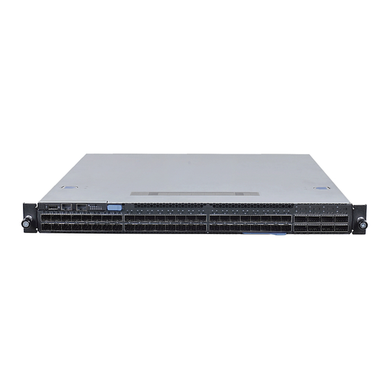
Page 15: Bes-53248 Series Switch
BES-53248 Series Switch BES-53248 Switch supports 48-port 25G SFP28 & 8-port 100G QSFP28 ports. Chassis for BES-53248 Series Switch Front panel Item Item USB Port System info. LED Console Port Power LED Link/Activity LED BMC LED Management Port SFP28 Port LEDs... - Page 16 State Description PSU1 & PSU2 LED LED number One per system on the front panel (bi-color – green & red) The unit is non-operational Red (Solid) Any one of PSUs is operating abnormally Red (Blinking) None Green (Solid) Both PSUs are operating normally Green (Blinking) None FAN LED...
-
Page 17: Data Port
State Description Management Port Link/ LED number One per unit on the front panel Activity LED No link (single-color – green) Green (Solid) The port is linked Green (Blinking) The port is linked and there is data activity LED on fan tray LED number One per fan tray (bi-color –green-red) -
Page 18: Ports Of Bes-53248 Series Switch
4 LEDs 50G Mode to two 50G ports are in yellow Ports of BES-53248 Series Switch The switch chassis is equipped with the following ports: • 48 SFP28 ports (10/25GbE) • 8 QSFP28 ports (10/25/40/50/100GbE speed) • 1 Management port •... -
Page 19: Data Port Connection
Data Port Connection Supported Cables and Transceivers See the following table for the list of supported cables and transceivers. Supported Description Note Distance 1G Direct Attach Cooper (DAC) cable SFP to SFP 1G Active Optical Cable (AOC) SFP to SFP 10G Direct Attach Cooper (DAC) cable SFP+ to SFP+ 10G Active Optical Cable (AOC) - Page 20 Push completely until the module locks into place. Repeat the above procedures to install additional SFP28 modules. For more information about the SFP28 port LED behavior when the network link is established, refer to “LED Indicators of BES-53248 Series Switch”. Network Switch Installation Guide...
-
Page 21: Fan Tray Of Bes-53248 Series
Repeat the above procedures to install additional QSFP28 modules. For more information about the QSFP28 port LED behavior when the network link is established, refer to “LED Indicators of BES-53248 Series Switch”. Fan Tray of BES-53248 Series The switch chassis is equipped with six fan trays. There are two types of hot-swappable fan modules. -
Page 22: Power Supply Of Bes-53248 Series Switch
Power Supply of BES-53248 Series Switch Equipped with two supply modules, the switch can operate with either one or two power supply modules. If the switch uses two power supply modules, you can hot-swap one of the PSU during the operations. -
Page 23: Airflow Direction
The hot air exhausts through the vents on the front panel of the switch. Operating Environment BES-53248 is restricted to be operated during the temperature 0~45°C, 90% maximum relative humidity, and 0 to 2952 ft operating altitude. Acoustic Report BES-53248 sound power value is shown below: Fan speed 40 duty ---->73 dBA... -
Page 24: Hardware Installation
Package Contents The following items are included with a standard package. When you open the box, check if all items are included and free of damage. • One BES-53248 Ethernet switch • Two AC power cords • Console cable • Rack mount ears •... -
Page 25: Positioning The Switch
• Ensure the rack or cabinet can support the weight of the switch and other additional weight. Positioning the Switch The switch is equipped with Power Supply Units (PSU) and hot-swappable fan modules. It is important to determine the airflow direction of the power supply and fan modules before installing the switch. - Page 26 Mounting the Switch into Standard Rack with BES-53248A1-SRMK Rail Kit Remove the inner rails. Pull the inner rail out until it is fully extended, and then push the tab forward to release the inner rail from the middle rail. Remove the inner rail. NOTE: •...
- Page 27 Remove the rail mounting brackets and screws from the accessory bag. Align the holes on the rail mounting brackets with the switch. Secure the rail mounting brackets with screws. Align the hooks on the switch with the holes in the inner rail, and then slide the inner rail backward until it is locked in place.
- Page 28 Install the outer rails to the rack. To install the front bracket: Pull the latch and install the rail by aligning the hooks √ with the front rack holes. Then release the latch to lock the hooks into place. To install the rear bracket: Align and push the rail firmly into the rear rack until √...
- Page 29 Secure the switch to the rack using the screws. Mounting the Switch into Ozeki Rack with BES-53248A1-ZRMK Rail Kit Remove the inner rails. Pull the inner rail out until it is fully extended, and then push the disconnect latch forward to release the inner rail from the middle rail. Remove the inner rail. Align the holes on the mounting ear with the inner rail.
- Page 30 Network Switch Installation Guide...
- Page 31 The switch supports front and rear rail installations. Align the hooks on the switch with the holes in the inner rail, and then slide the inner rail backward until it is locked in place. Secure the inner rail to the switch with the screws. Front Installation Rear Installation NOTE:...
-
Page 32: Connecting To The Console Port
NOTE: • Push the disconnect latch to release the switch when removing the switch and it is fully extended. Connecting to the Console Port The console port is used for setting up and managing the switch via a connection to a console terminal or PC using a terminal emulation program. -
Page 33: Connecting To The Management Port
To connect to the console, do the following: Connect the RJ-45 connector to the console port ( ) of the switch. Connect the DB9 to a terminal or PC. Manage the switch using the CLI commands (refer to the CLI User Manual for more information). -
Page 34: Connecting The Power
Connecting the Power CAUTION • Ensure that the socket outlet is installed near the equipment and be easily accessible. • The power cord must have safety ground pin or contact that is suitable for the electrical outlet. The power supply cord(s) must be plugged into socket outlet(s) that •... -
Page 35: Components Replacement
Components Replacement Troubleshooting Below is a list of the common problems that you may encounter when using the switch. Try to solve these problems with the suggested solutions before calling for service. If problems persist, contact customer support. Diagnostic Switch Indicator Problem Solution Power LED is off. -
Page 36: In-Band Access
In-Band Access You can access the management agent in the switch from anywhere within the attached network using Telnet, a Web browser, or other network management software tools. However, you must first configure the switch with a valid IP address, subnet mask, and default gateway. -
Page 37: Replacing The Fan Tray
Replacing the Fan Tray CAUTION When installing a new fan module, make sure it has the same airflow direction • as the fan modules and the power supply. The fan modules can be replaced without the use of special tools. Before replacing any of the fan modules, verify the status of the fan modules to determine if there is a need for replacement. - Page 38 NetApp. The use or purchase of this product does not convey a license under any patent rights, trademark rights, or any other intellectual property rights of NetApp.
Need help?
Do you have a question about the BES-53248 and is the answer not in the manual?
Questions and answers
What is the command to check powersupply