Table of Contents
Advertisement
Quick Links
Hydraulic unit
HY-Ex
English translation of the original German operating
instructions
for qualified and authorized operating personnel
Status 11/2017
Always store these operating instructions together at the hydraulic unit. Ensure that the operating instructions
are available for the qualified and authorized operating personnel. Read and comply with the operating
instructions.
Non-observance can lead to injury and possibly death.
Advertisement
Table of Contents

Related Manuals for Hytorc HY-Ex


Summary of Contents for Hytorc HY-Ex
- Page 1 Hydraulic unit HY-Ex English translation of the original German operating instructions for qualified and authorized operating personnel Status 11/2017 Always store these operating instructions together at the hydraulic unit. Ensure that the operating instructions are available for the qualified and authorized operating personnel. Read and comply with the operating instructions.
- Page 2 Issue date 11/10/2017 Copyright © 2017, HYTORC Technologies GmbH All rights, including those of reprinting and reproduction of any parts of this document and its translation, are reserved by the publisher. No part of this document may be reproduced in any form or copied using electronic reproduction systems without the written consent of the publisher.
-
Page 3: Table Of Contents
Table of contents Notes concerning this manual and the manufacturer ..........6 Keep the manual available ..................... 6 Design features of this manual ..................6 Referenced documents ....................7 Manufacturer's address ....................7 Person responsible for documentation ................7 Warranty and liability ...................... 8 Safety ........................ - Page 4 Design characteristics of warning information .............. 19 Design of information about property damage ............. 20 Warning and information signs ..................21 Description ......................23 Directional data ......................23 Overview front right ....................... 24 Overview rear right ....................... 25 Overview of the hydraulic unit with one tool connection ..........26 Layout ...........................
- Page 5 After use ......................... 49 Decommissioning the unit ..................51 Servicing the unit ....................52 Maintenance schedule ....................52 Changing the hydraulic oil .................... 53 Cleaning the unit ....................57 Remedying faults or malfunctions ................ 58 Table of faults ....................... 58 Replacing fuses ......................
-
Page 6: Notes Concerning This Manual And The Manufacturer
Notes concerning this manual and the manufacturer These instructions help using the HY-Ex hydraulic unit safely. The HY-Ex hydraulic unit is hereinafter referred to as "unit". Keep the manual available These operating instructions are a part of the unit. Make sure that the operating instructions are always accessible for the user at the site and are in legible condition. -
Page 7: Referenced Documents
Declarations of conformity or declarations of incorporation Please heed and comply with the information from the applicable documents. These can be found in the documentation folder of the unit. Manufacturer's address HYTORC Technologies Kleinbeckstr 3–17 45549 Sprockhövel Germany Telephone: +49 (0) 23 24-90 77-0 Fax: +49 (0) 23 24-90 77-99 E-Mail: info@hytorctech.com... -
Page 8: Warranty And Liability
Notes concerning this manual and the manufacturer Warranty and liability In general our General Terms and Conditions apply. Warranty and liability claims for personal injury or property damage are always excluded if they are due to one or more of the following causes: ... -
Page 9: Safety
Safety Safety WARNING Severe injuries or death caused by accidents due to disregard of the instructions in this guide. In particular the failure to observe the instructions in the Chapter on Safety, can lead to accidents. Read and follow all instructions in this manual before you begin working with or on the unit. -
Page 10: Equipment Category (2)
Safety Equipment category (2) Equipment category II comprises equipment that was designed in such a way that ensures a high level of safety if the equipment is used as intended with the prescribed parameters. Equipment of this category can be used in areas where a potentially explosive atmosphere of gases, vapors, mists or dust/air mixtures occurs occasionally. -
Page 11: Equipment Protection Level (6)
ATEX marking of the unit According to DIN EN ISO 80079-36. 2016, Section 11: EX II 2 G Ex h IIB T3 Gb This ATEX marking is valid for the following HY-Ex unit types: 115 V:1PH100–115/50 Hz 115 V:1PH100–115/60 Hz ... -
Page 12: Responsibilities Of The Operating Company
Safety Responsibilities of the operating company The operator must ensure that all accident prevention regulations are complied with. The operator must ensure that only qualified and authorized operating personnel performs work on and with the unit. Persons at particular risk The following groups of persons must not be granted access to the unit as they might sustain serious or lethal injuries: ... -
Page 13: Qualification Of Personnel
Safety Qualification of personnel These operating instructions are addressed to qualified and authorized operating personnel. The following sections list the necessary qualification for each activity on or with the unit. Power supply connection The following skills and experience are required for the operating personnel: ... -
Page 14: Assessing The State Of The Unit
Safety Assessing the state of the unit The following skills and experience are required for the operating personnel: have been taught and trained for the work know that improper operation, maintenance and repairs can cause accidents can asses hazards that arise from electrical voltage and power ... -
Page 15: Personal Protective Equipment
Safety Personal protective equipment Feet may be crushed when moving the unit. Wear safety shoes with steel toe caps. Slipping and thereby risk of fractures when performing hydraulic work is possible! Wear safety shoes with non-slip soles. Skin irritation and eye damage when in contact with hydraulic oil and hydraulic components is possible! ... -
Page 16: Preventing Electric Shock
Safety Preventing electric shock Severe injury or death from electrical shock is possible! Check the electrical supply line for damage. Use the unit only with immaculate lead. Immediately have a damaged electrical lead replaced by authorized personnel. ... -
Page 17: Preventing Poisoning
Safety Preventing poisoning The unit may overheat. In this case, oil mist and oil vapors can form. Make sure there is sufficient ventilation. In poorly ventilated areas and upon formation of oil mist and oil vapors, wear a respirator. ... -
Page 18: Preventing Skin Irritation
Safety Preventing skin irritation Contact with hydraulic oil may cause skin irritation. Always provide a strong and tight connection between the unit and hydraulic tools. Wear nitrile gloves at work where you might come in contact with hydraulic oil. -
Page 19: Design Characteristics Of Warning Information
Safety Design characteristics of warning information DANGER Sections with the word DANGER warn of imminent dangerous situations that lead to death or serious injury. WARNING Sections with the word WARNING warn of imminent dangerous situations that may lead to death or serious injury. CAUTION Sections with the word CAUTION warn of dangerous situations that may lead to minor or moderate injuries. -
Page 20: Design Of Information About Property Damage
Safety Explanation of symbols Hazard from electric shock Slipping hazard from leaked media Burning hazard, scalding hazard Risk of explosion in potentially explosive areas Risk of eye damage due to splashing liquid Risk of explosion and explosive media discharge Design of information about property damage ATTENTION! These notes warn of situations that can lead to property damage and limited functionality. -
Page 21: Warning And Information Signs
Safety Warning and information signs Make sure that all warnings and signs attached to the unit are clearly visible and legible. Replace damaged or lost warnings and signs immediately. The following labels are affixed to the unit: Warning or information sign Meaning or explanation ... - Page 22 Safety Warning or information sign Meaning or explanation Switch off the unit when not in use. Use the torque valve only when hydraulic hoses are connected.
-
Page 23: Description
Description Description The hydraulic unit can be delivered with one or four tool connections. It is possible for you to expand an existing hydraulic unit with one tool connection to four tool connections. For this, please contact the manufacturer. The illustrations and descriptions in this manual refer to a hydraulic unit with four tool connections. -
Page 24: Overview Front Right
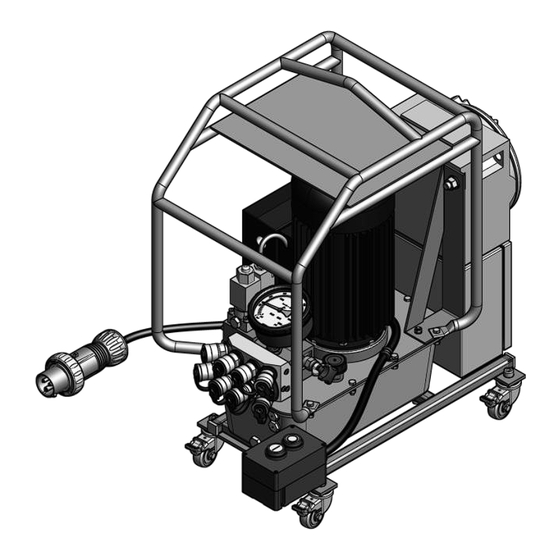
Description Overview front right Name Roof on top of the electric motor Ventilation and bleed valve Oil filler neck Stop button (switch unit to Standby mode) Start button (build pressure, actuate connected tool) Remote control Couplings (return stroke) Power plug Couplings (forward stroke) Solenoid valve Pressure gage... -
Page 25: Overview Rear Right
Description Overview rear right Name Protective bar Pressure-resistant electric control housing Cover Oil inspection glasses Oil drain screw Lockable rollers Terminal box Oil container Base frame Torque valve Electric motor of motor pump unit... -
Page 26: Overview Of The Hydraulic Unit With One Tool Connection
Description Overview of the hydraulic unit with one tool connection Name Coupling (return stroke) Coupling (forward stroke) Layout The unit consists of the following main components: Electric motor pump unit Oil container Valve block Oil cooler ... -
Page 27: Display And Operating Elements
Description Display and operating elements Pressure gage The pressure gage (1) shows the current pressure in bar or psi. Couplings The couplings are arranged on the front side of the unit. The couplings are used to connect the tools. Using screw caps provides a tight connection between the tool and the unit. -
Page 28: Remote Control
Description Remote control The remote control is used to: Switch the pump on and off Operate the tool Remote control functions: In Standby mode: The motor is started. The connected screwing tool is moved into the starting Press the Start button (1), then position (return stroke). -
Page 29: Torque Valve
Alternatively, visit the download area on the HYTORC website. If necessary, loosen the wing nut. To increase the pressure, turn the T-handle of the torque valve clockwise. -
Page 30: Available Accessories
Your local HYTROC branch will provide you with information on suitable screwing tools. The use of HYTORC standard screwing tools with the unit is permitted outside of the potentially explosive area. Workspaces and positions... -
Page 31: Purpose And Function
Description Purpose and function The unit is used to drive hydraulic screwing tools. A screwing tool can be connected to the design with two couplings. Up to four screwing tools of the same type can be connected simultaneously to the design with eight couplings. The upper four couplings are designed as male connectors and are responsible for the feed stroke of the connected screwing tools. -
Page 32: Unpacking And Checking The Delivery
Unpacking and checking the delivery Unpacking and checking the delivery Unpacking The unit is supplied in a cardboard box on a disposable pallet. The cardboard box is secured onto the disposable pallet with two tensioning straps. To unpack the unit, proceed as follows: ... -
Page 33: Storing The Unit
Storing the unit Storing the unit Store the unit in an upright position on its locked rollers in a dry, dust-free room with stable temperature. The permissible temperature range is –30 °C to +60 °C (–22 °F to +140 °F). The humidity may not be condensing. -
Page 34: Moving The Unit
Moving the unit Moving the unit To move the unit on site, proceed as follows: Release the roller lock. Hold the unit with both hands at the protective bar. Push the unit to the desired position. Lock the rollers. -
Page 35: Commissioning The Unit
Commissioning the unit Commissioning the unit When commissioning the unit, we distinguish between the initial commissioning and daily commissioning. Depending on the type of commissioning, you must perform different work tasks. Initial commissioning For initial commissioning, perform the work outside of the potentially explosive area. - Page 36 Commissioning the unit To fill the hydraulic oil in the oil tank of the unit, proceed as follows: Make sure that the unit stands securely on a flat surface. Remove the bleed and ventilation valve (1) of the unit's filling opening. ...
-
Page 37: Daily Commissioning
Commissioning the unit Daily commissioning In daily use, you must perform the following tasks: Remove protective caps and plugs and connect tools Connect mains plug Bleed screw system consisting of unit, hose and tool Check oil level ... - Page 38 Commissioning the unit Before you can connect a tool, you must remove the protective cap and the protective plug of two stacked couplings. Proceed as follows: Screw the safety cap (2) counterclockwise from the corresponding connection (1). Screw the protective plug (3) counterclockwise from the corresponding connection (4).
-
Page 39: Connect Mains Plug
Commissioning the unit To connect a tool to the unit, proceed as follows: Ensure that the hydraulic hoses are not damaged. Plug the male connector (3) on the hydraulic hose of the tool on the female connection (4) of the unit. ... -
Page 40: Bleeding The Screw System (Generator, Hose, Tools)
Commissioning the unit Bleeding the screw system (generator, hose, tools) When connecting the tools, air can pass into the hydraulic circuit. To ensure a smooth and safe operation, you need to vent the screw system. Proceed as follows: Press and release the button (1) on the remote control several times. The connected screwing tool moves back and forth. -
Page 41: Checking Functioning Of The Manometer
Commissioning the unit The manufacturer-approved oils can be found starting on page 67. To check the oil level, proceed as follows: Make sure that the unit stands securely on a flat surface. Check if the hydraulic oil is visible in the upper sight glass. ... -
Page 42: Operating The Unit
Operating the unit Operating the unit To operate the unit, proceed as follows: Make sure that the unit stands on a dry, level, solid and stable base. Turn the torque valve counterclockwise and set the pressure to 0 bar. Changing tools DANGER Risk of explosion when connecting and removing tools. - Page 43 Operating the unit Press the button (1) stop on the remote control several times, if need be. The unit is in stand-by. The pressure decreases. Wait until the pressure gage pressure shows no pressure anymore. Press the button (1) stop several times if necessary. ...
- Page 44 Operating the unit If you want to install the new tool at the same couplings, proceed as follows: Plug the male connector on the hydraulic hose of the tool on the female connection of the unit. Screw the connection with the union nut hand-tight. ...
- Page 45 Operating the unit Before you can connect a tool, you must remove the protective cap and the protective plug of two stacked couplings. Proceed as follows: Screw the safety cap (2) counterclockwise from the corresponding connection (1). Screw the protective plug (3) counterclockwise from the corresponding connection (4).
-
Page 46: Setting The Pressure
Operating the unit Setting the pressure WARNING Risk to life from incorrect procedure when setting the pressure on the unit. Faulty adjustment of the pressure causes an incorrect adjustment of the torque for the screwing process. Always set the pressure from a low value to a high value. CAUTION Risk of eye damage during pressure of more than 700 bar (10,000 psi) - Page 47 Operating the unit The current pressure is visible on the pressure gage. If the pressure exceeds the required value, release the push button start. Turn the torque valve (1) counter-clockwise. Press the button start again to display the current pressure. ...
-
Page 48: Performing A Screwing Process
Operating the unit Performing a screwing process To perform a screwing process, proceed as follows: Ensure that the screwing tool is connected. Ensure that the pressure required for the screw connection is set on the unit. Place the screwing tool onto the screw connection so that the tool cannot fall off. -
Page 49: After Use
After use After use DANGER Risk of explosion when connecting and removing tools. Connecting tools to or removing tools from the unit in the potentially explosive area can lead to serious injury or death. Only connect tools to the unit outside of the potentially explosive area. - Page 50 After use To remove the connected screwing tools, proceed as follows: Loosen the union nut (2). Pull the female connector (2) from the male connector (1) of the unit. Loosen the union nut at the female connector (4). ...
-
Page 51: Decommissioning The Unit
Decommissioning the unit Decommissioning the unit To take the unit out of operation for more than three months, proceed as follows: Switch off the unit by pressing the button stop of the remote control. Unplug the power cord from the wall outlet. ... -
Page 52: Servicing The Unit
Servicing the unit Servicing the unit Maintenance schedule Interval Component Action prior to every operation Electrical connection lines Check electrical connection cables for visible damage, twists and kinks. Eliminate twists. Have defective or kinked electrical leads replaced by qualified personnel. -
Page 53: Changing The Hydraulic Oil
Servicing the unit Changing the hydraulic oil DANGER Risk of explosion when carrying out maintenance work. Carrying out maintenance work in the potentially explosive area can lead to serious injury or death. Only carry out maintenance work outside of the potentially explosive area. - Page 54 Servicing the unit To change the hydraulic oil, proceed as follows: Always switch off the unit with the button (1) stop on the remote control.
- Page 55 Servicing the unit Unplug the power cord from the wall outlet. Remove attached screwing tools from the couplings, see page 49. Place the unit on a solid flat surface, for you to be able to put a container under the oil drain plug.
- Page 56 Servicing the unit To fill the hydraulic oil in the oil tank of the unit, proceed as follows: Make sure that the unit stands securely on a flat surface. Remove the bleed and ventilation valve (1) of the unit's filling opening. ...
-
Page 57: Cleaning The Unit
Cleaning the unit Cleaning the unit DANGER Risk of explosion when carrying out maintenance work. Carrying out maintenance work in the potentially explosive area can lead to serious injury or death. Only carry out maintenance work outside of the potentially explosive area. -
Page 58: Remedying Faults Or Malfunctions
Remedying faults or malfunctions Remedying faults or malfunctions Table of faults Fault Possible cause Remedy The pump does not Electric components Have the electrical work. are damaged. components checked and, if necessary, replaced by qualified personnel. The power supply is ... - Page 59 Remedying faults or malfunctions Fault Possible cause Remedy The pressure is less The solenoid valve is Have the solenoid valve than 70 bar. defective. checked electrically by qualified personnel. Have the solenoid valve checked hydraulically by qualified personnel. ...
- Page 60 Remedying faults or malfunctions Fault Possible cause Remedy The pressure is only The solenoid valve is Have the solenoid valve 70 – 80 bar. defective. checked electrically by qualified personnel. Have the solenoid valve checked hydraulically by qualified personnel. ...
- Page 61 Remedying faults or malfunctions Fault Possible cause Remedy The max. pressure of The torque valve is Have the torque valve 700 bar is not reached, defective. checked for proper condition though no visible leaks by qualified personnel. are present. ...
-
Page 62: Replacing Fuses
Remedying faults or malfunctions Replacing fuses DANGER Risk of explosion when carrying out maintenance work. Carrying out maintenance work in the potentially explosive area can lead to serious injury or death. Only carry out maintenance work outside of the potentially explosive area. -
Page 63: Replace 115 V/230 V Fuse
Remedying faults or malfunctions Replace 115 V/230 V fuse Remove fuse (1) F1. Check the condition of the fuses with a multimeter. If the fuse is defective, replace it. Make sure that the new fuse is of the same type and capacity as the fuse to be replaced. -
Page 64: Replace 400 V Fuse
Remedying faults or malfunctions Replace 400 V fuse Remove fuses (1) F1, F2 and F3. Check the condition of the fuses with a multimeter. If one or several fuses are defective, replace them. Make sure that the new fuses are of the same type and capacity as the fuses to be replaced. -
Page 65: Disposal
Disposal Disposal In the USA Observe and follow the regulations for disposal. If in doubt, please consult your municipal or local authority. WARNING Risk of poisoning from hydraulic oil Hydraulic oil can contaminate ground water and soil. Always dispose of hydraulic oil in an environmentally friendly manner using a specialist firm. -
Page 66: In Europe
Disposal In Europe Observe and follow the regulations for disposal. If in doubt, please consult your municipal or local authority. WARNING Risk of poisoning from hydraulic oil Hydraulic oil can contaminate ground water and soil. Always dispose of hydraulic oil in an environmentally friendly manner using a specialist firm. -
Page 67: Technical Specifications
Technical specifications Technical specifications Dimensions and weights (one tool connection) Width: 623 mm (24.5 in) Height: 647 mm (25.5 in) Depth: 328 mm (13.0 in) Weight: approx. 51.0 kg (112.0 lbs) (without oil fill), 400 V approx. 71.0 kg (157.0 lbs) (without oil fill), 115/230 V Dimensions and weights (four tool connections) Width: 623 mm (24.5 in) - Page 68 Technical specifications Information about the hydraulics Oil recommendation Hyspin HVI 32, alternatively Bio- Hydraulic oil on mineral oil basis, e. g., Shell Naturella HFE Recommended viscosity grades: Starting at +10 °C (50 °F) 32-46 mm²/s, below +10 °C (50 °F) 15-22 mm²/s Tank volume: 8 l (2.1 US.liq.gal) Working pressure:...
Need help?
Do you have a question about the HY-Ex and is the answer not in the manual?
Questions and answers