Table of Contents
Advertisement
Quick Links
EP1502 Intelligent Controller
with Two Reader Interface
Installation and Specifications:
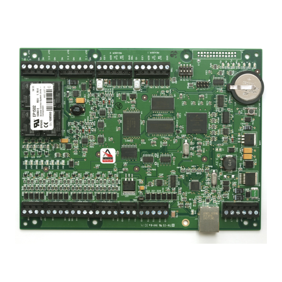
1. General
The EP1502 intelligent controller provides decision making, event reporting, and database storage for the
Mercury hardware platform. Two reader interfaces provide control for two doors.
It communicates with the host via on-board 10-BaseT/100Base-TX Ethernet port. Alternatively, port 1
(RS-232) can be used for host communication.
Two physical barriers can be controlled with the EP1502. Each reader port can accommodate a read-
head that utilizes Wiegand, magnetic stripe, or 2-wire RS-485 electrical signaling standards, one or two
wire LED controls, and buzzer control (one wire LED mode only). Four Form-C relay outputs may be
used for strike control or alarm signaling. The relay contacts are rated at 5 A @ 30 Vdc, dry contact
configuration. Eight inputs are provided for monitoring the door contacts, exit push buttons and alarm
contacts. The EP1502 requires 12-24 Vdc for power. It is recommended that the EP1502 be mounted
.25" minimum above any conductive surface.
2. EP1502 Hardware:
8.00 [203.20]
Mercury Security Corporation © 2011
2355 MIRA MAR AVE. LONG BEACH, CA 90815-1755, (562)986-9105 FAX (562) 986-9205
BATTERY: BR/CR2330
REPLACE ANNUALLY
STATUS LED's
.50 [12.70]
1
2
J4
3
TMP
FLT
R1
R2
2.00 [50.80]
+
-
J3
J8
1
2
3
4
S1
TB8
GND
DAT
D0
CLK
D1
BZR
3.00 [76.20]
LED
VO
TB9
GND
DAT
D0
CLK
D1
BZR
LED
VO
PASS
12V
NO
J7
OUT 1 C
NC
NO
OUT 2 C
2.00 [50.80]
NC
NO
OUT 3 C
NC
NO
OUT 4 C
.50 [12.70]
NC
.25 [6.35]
RELAY
STATUS
LED's
EP1502
This device complies with part 15 of the FCC Rules.
Operation is subject to the following two conditions: (1) This
device may not cause harmful interference, and (2) this
device must accept any interference received, including
interference that may cause undesired operation.
RESET SWITCH
3V
BR/CR2330
S2
BT1
J1
5V
3.3V
1
2
3
4
VBAT
8V
K2
K1
IN1
IN2
IN3
K
IN4
1
K
IN5
2
IN6
K
3
IN7
K
4
IN8
K4
K3
5.50 [139.70]
6.00 [152.40]
INPUT
STATUS
LED's
DOC 10107-0031
www.mercury-security.com
Ø.156 [3.96]
8 PLACES
TB1
VIN
TMP
GND
FLT
GND
ETHERNET
SHIELD
J6
TB2
TXD
RXD
RTS
CTS
GND
TR+
TR-
GND
TB4
IN1
IN2
IN3
IN4
TB5
TB6
IN5
IN6
TB7
IN7
IN8
.25 [6.35]
REV 1.05
Page 1
Advertisement
Table of Contents

Related Manuals for Mercury EP1502


Summary of Contents for Mercury EP1502
- Page 1 It communicates with the host via on-board 10-BaseT/100Base-TX Ethernet port. Alternatively, port 1 (RS-232) can be used for host communication. Two physical barriers can be controlled with the EP1502. Each reader port can accommodate a read- head that utilizes Wiegand, magnetic stripe, or 2-wire RS-485 electrical signaling standards, one or two wire LED controls, and buzzer control (one wire LED mode only).
- Page 2 TB6 Input 5 NC: Normally Closed Contact Input 6 TB7 Input 7 Input 8 Jumpers: The EP1502 processor hardware interface is configured using jumpers to setup the port interface and end of line termination. JUMPERS SET AT DESCRIPTION Factory Use Only...
- Page 3 DIP Switches: The four switches on S1 DIP switch configure the operating mode of the EP1502 processor. DIP switches are read on power-up except where noted. Pressing switch S2 causes the EP1502 to reset. Definitions Normal operating mode. After initialization, enable default User Name (admin) and Password (password).
- Page 4 12 Vdc (VIN must be greater than 20 Vdc), or power is passed-through (PT) from the input voltage of the EP1502 (TB1-VIN) and is current limited to 150 mA for each reader port. Readers that require different voltage or have high current requirements should be powered separately.
- Page 5 Diode breakdown voltage: 4x strike voltage For 12 Vdc or 24 Vdc strike, diode 1N4002 (100V/1A) typical. MOV Selection: Clamp voltage: 1.5x Vac RMS. For 24 Vac strike, Panasonic: ERZ-C07DK470 typical Mercury Security Corporation © 2011 EP1502 DOC 10107-0031 REV 1.05 Page 5...
- Page 6 Relay K4: ON = Energized Note 1: If this input is defined, every three seconds the LED is pulsed to its opposite state for 0.1 seconds, otherwise, the LED is off. Mercury Security Corporation © 2011 EP1502 DOC 10107-0031 REV 1.05...
- Page 7 10 to 95% RHNC Mechanical: Dimension: 8 in (203.2 mm) W x 6 in (152.4 mm) L x 1 in (25 mm) H Weight: 9 oz (255 g) nominal, board only Mercury Security Corporation © 2011 EP1502 DOC 10107-0031 REV 1.05 Page 7...
- Page 8 This product is not intended for, nor is rated for operation in life-critical control applications. Mercury Security Corporation is not liable under any circumstances for loss or damage caused by or partially caused by the misapplication or malfunction of the product. Mercury Security Corporation's liability does not extend beyond the purchase price of the product.
Need help?
Do you have a question about the EP1502 and is the answer not in the manual?
Questions and answers