Table of Contents
Advertisement
Advertisement
Table of Contents

Related Manuals for jcb Access Series

Summary of Contents for jcb Access Series
- Page 1 Quick Start Guide JCB Access Electric Scissors...
- Page 2 This machine should not be operated by any person who isn’t appropriately qualified or had the appropriate training. > Operation of this machine without periodic maintenance could cause it to malfunction. For more information please contact your JCB Dealer. Please see operator manual for full details.
-
Page 3: Table Of Contents
Index Intended Use ............................4 Nomenclature ............................5 Tie Down Points ..........................6 Lifting Points ........................... 7-8 Operating Capabilities ........................9 Ground Controls ..........................10 Platform Controls ..........................11 Emergency Controls .........................12 Operating from the Ground ......................13 Operating from the Platform ......................14 Extending Deck & Power to Platform ....................15 Machine Sensors..........................16 Daily Checks.............................17 Charge Level &... -
Page 4: Intended Use
Intended Use General > Machine Type – Electric Scissor > Self propelled machine with platform height of 15ft – 45ft (4.6m – 13.8m) > Lead acid or lithium battery powered Intended Use > Machine intended to be used in normal conditions as detailed in the operators manual >... -
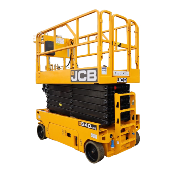
Page 5: Nomenclature
Nomenclature Scissor Platform height (ft) Width (in) Electric 9 Models S1530E S1930E S2032E S2046E S2632E S2646E S3246E S4046E S4550E ELECTRIC SCISSORS... -
Page 6: Tie Down Points
Tie Down Points There are tie down points around all four corners of the machine. Look for this decal. Make sure locking pins are engaged during loading/ transport of the machine. Operation Fig 1 Transporting the Machine A Lock Pin Figure 31. -
Page 7: Lifting Points
Lifting Points Lifting by hoist You must consider the location of the centre of gravity on the machine (see table on page 8), when you lift the machine Make the machine safe with the platform lowered Check the extension platform, controller and chassis parts are correctly secured Remove any loose items from the machine Use the correct length of hoisting rope to prevent damage to the platform base &... - Page 8 Lifting Points Operation Lifting the Machine Lifting the Machine Location of the centre of gravity General Machine Model X Axis Y Axis S1530E 620mm 511mm Lifting by Forklift S1930E 604mm 540mm S2032E 955mm 625mm Do not lift the machine from the side. Lifting the machine from the side may cause machine damage. S2632E 956mm 672mm...
-
Page 9: Operating Capabilities
Operating Capabilities The machine has been designed to operate in atmospheric temperatures between -20ºC and 46ºC. The machine is designed to be used on flat level surfaces. The machine will operate with a front/back slope of up to 3º and a side slope of up to 1.5º. Exceeding these limits will trigger the tilt alarm. The load capacity and wind rating of each machine can be found on the entry gate and also on the deck plate next to the handbook box. -
Page 10: Ground Controls
Ground Controls Fig 5 A Hourmeter B Platform Raise / Lower Toggle Switch C Emergency Stop D Ground Controls / Off / Platform Controls Key Switch Please see operator manual for full details. -
Page 11: Platform Controls
Platform Controls Fig 6 A L / R Steering B Trigger Switch to enable operation C Battery Level / Fault Code Display D Platform / Drive Mode Buttons E Horn F Speed Select G Emergency Stop ELECTRIC SCISSORS... -
Page 12: Emergency Controls
Emergency Controls Fig 7 A Brake Release Lock B Brake Release Pump C Pull to lower How to Release Brakes Ensure machine can be controlled before releasing brakes Push in brake release lock Pump brake release until feels solid Caution – machine is now un-braked To reapply pull the brake release lock back out or operate any control on the joystick Please see operator manual for full details. -
Page 13: Operating From The Ground
Operating from the Ground Connect Isolator Pull E-Stops The isolator is located within the battery tray Ensure both the ground controls and platform on the left hand side of the machine. controls E-stops are released. Switch Key Left Toggle Switch Turn the key switch left to enable Use the toggle switch to raise or lower the ground controls. -
Page 14: Operating From The Platform
Operating from the Platform Connect Isolator Pull E-Stops Switch Key Right The isolator is located within Ensure both the ground Turn the key switch right to the battery tray on the left controls and platform controls enable the platform controls. hand side of the machine. -
Page 15: Extending Deck & Power To Platform
Extending Deck & Power to Platform All JCB Electric Scissors are fitted with both power to platform and an extending deck as standard. The extending deck is operated by the pedal on the deck. The power to platform is used by the plug on the right hand side near the ladder and the power outlet in the basket (Photo for illustrative purposes, plugs and sockets region specific). -
Page 16: Machine Sensors
Machine Sensors Safety systems on the electric scissor range rely on various sensors positioned around the machines linked to the on-board ECU. Angle Sensor Tilt Sensor Pothole Protection Switch Pressure Sensors Limit Switches Please see operator manual for full details. -
Page 17: Daily Checks
Daily Checks Check Operators Manual Check Condition Safety Decals Check Condition Hydraulic Oil Check Level / No Leaks Battery Electrolyte Check Level / No Leaks Electrical Harnesses Check Condition Welds Check Condition Machine Damage, Missing Parts Check Condition Guard Rails Check Condition Wheel Nut Split Pin Check Condition... -
Page 18: Charge Level & Charging
Charge Level & Charging The machine charge level is shown on the platform controller only when in platform mode. A series of red bars are used to show the charge level, 6 being full, 1 being empty. Fig 8 Full charge 30% Remaining Charge battery low Battery too low. - Page 19 Charge Level & Charging The machine is charged using the plug on the left hand side, as viewed from the entry side of the machine. Once plugged in, green LED lights will start to flash on the charger, viewed through the charger viewing window.
- Page 20 Charge Level & Charging The flashing LED indicates the charge level. When all three LEDs are solid, the machine is fully charged. Fig 10 Note: Only use the original charger installed to the machine with the original batteries. Charge the battery in a well ventilated place.
-
Page 21: Service Points
Maintenance Service Points Service Points Service Points General Hydraulic Compartment Fig 11 Figure 35. Hydraulic Tray A Main control relay B Hydraulic oil level indicator sight hole C Hydraulic oil filler cap D Hydraulic oil filter A Ignition Relay E Ground Control Connection E Platform control connection F Hydraulic breather B Hydraulic Level Viewing Window... -
Page 22: Diagnostic Codes
Restart the machine Limp mode Lift slow to elevated speed Check battery charge level Platform left turn switch ON at Diagnostic message only Contact JCB dealer power-up message Platform right turn switch on at Diagnostic message only Contact JCB dealer power-up message... - Page 23 Drive forward coil fault Disable lifting and driving operated at start-up Drive reverse coil fault Disable lifting and driving Contact JCB dealer Lift up coil fault Disable lifting and driving Contact JCB dealer Lift down coil fault Disable lifting and driving...
- Page 24 They should not therefore be relied upon in relation to suitability for a particular application. Guidance and advice should always be sought from your JCB Dealer’. JCB reserves the right to change specifications without notice. Illustrations and specifications shown may include optional equipment and accessories.
Need help?
Do you have a question about the Access Series and is the answer not in the manual?
Questions and answers