
Related Manuals for HEK MS 3000

Summary of Contents for HEK MS 3000
- Page 1 USER'S MANUAL MS 3000 MAST CLIMBING WORK PLATFORM This manual is assigned to: Issue: 02-2000 9095-032A...
- Page 2 © 2000, HEK Manufacturing BV., Middelbeers, The Netherlands Nothing contained in this publication may be copied, and/or published by means of printing, photocopying, microfilm or any other method without prior written permission from HEK Manufacturing B.V. MS 3000 • 9095-032A...
- Page 3 HEK Manufacturing B.V. Westelbeersedijk 18 P.O. box 2 5091 SM Middelbeers 5090 AA Middelbeers The Netherlands The Netherlands : +31 13 51 48 653 Fax : +31 13 51 48 630 MS 3000 • 9095-032A...
- Page 4 MS 3000 • 9095-032A...
- Page 5 This instruction manual describes only the basic machine, in the standard form supplied by HEK Manufacturing BV. Read this instruction manual carefully before using the mast climbing work platform. Take all the safety precautions as described in chapter 3 into account.
-
Page 6: Table Of Contents
Ground support Positioning the mast climbing work platform 6.3.1 Positioning the mast climbing work platform Assembly of the mast Anchoring the mast 6-10 Adjusting the platform width 6-12 Adjusting the EMOS system 6-14 Lightning protection 6-14 MS 3000 • 9095-032A... -
Page 7: Contents
6-14 Fig.7-1 Main switch Fig.7-2 Emergency push-button Fig.7-3 Brake lever platform Fig.7-4 Push-buttons control box Fig.7-5 Brake lever platform Fig.8-1 Brake lever platform Fig.8-2 Locking pin outrigger Fig.8-3 Locking pin outrigger chassis Fig.9-1 Motorbrake Fig.9-2 Motorbrake MS 3000 • 9095-032A... -
Page 8: Ec Declaration Of Conformity
EC Machine Directives 89/392/EG, Annex IV, including 91/368, 93/44 EC number: 08/205/A 16-4912C, 06-01-1997 Certified by (‘Notified Body’): TÜV HANNOVER/SACHSEN ANHALT E.V. HANNOVER, GERMANY Date/Manufacturer’s signature: Middelbeers, the Netherlands, November 1st 1999 Signatory: P.M. Blom, deputy manager VIII MS 3000 • 9095-032A... -
Page 9: Meaning Of The Symbols Usedi
Failing to (exactly) comply with the working or operating instructions may lead to serious injury, fatal accident, severe mechanical damage or operating losses. During use, no person may stand under the machine. Danger: High voltage. Danger of falling objects. MS 3000 • 9095-032A... - Page 10 Fig.1 Dimensions MS 3000 • 9095-032A...
-
Page 11: Technical Details
The details are based on standard applications. In special situations, it may be possible to deviate from these. This may only be done with the prior written approval of the supplier. For accessories and options see the accessory book. MS 3000 • 9095-032A... -
Page 12: Fig.1-1 Platform Components
TECHNICAL DETAILS Fig.1-1 Platform components Fig.1-2 Mast element Fig.1-3 Fence posts MS 3000 • 9095-032A... - Page 13 C = Plug-in fence 175 D = Plug-in fence 150 E = End fence F = Gate G = Lengthwise post H = Gate side post I = End side post J = Mast element 150 MS 3000 • 9095-032A...
- Page 14 TECHNICAL DETAILS Fig.1-4 Chassis MS 3000 • 9095-032A...
-
Page 15: Electrical Installation
Dimension F 2040 - 2810 mm Dimension G 668 - 968 mm Dimension H 490 - 605 mm Weight 1480 kg Tyre pressure 5 bar Height of the platform from the ground Depending of lower striker plate MS 3000 • 9095-032A... -
Page 16: Platform Construction, Loading Diagrams And Emos Program Numbers
175 may be attached. The permitted loading situations are described in sections 1.4.1 and 1.4.2. The P numbers in section 1.4.1 are the EMOS program numbers. 1.4.1 Maximum loading platform construction 1.4.2 Maximum eccentrically loading platform construction MS 3000 • 9095-032A... -
Page 17: Anchor Forces
The forces Al and Bl are calculated forces parallel to the facade. The forces Ad and Bd are calculated forces perpendicular to the facade (these forces may either be in tension or compression). The forces Ap and Bp are the calculated forces in the anchor tubes. MS 3000 • 9095-032A... - Page 18 TECHNICAL DETAILS MS 3000 • 9095-032A...
-
Page 19: Component Description
The platform can be adjusted to suit the required working situation with the use of separate platform elements. The width of the platform can be adjusted by means of outriggers. Fig.2-1 Basic set MS3000 MS 3000 • 9095-032A... - Page 20 The simple construction ensures that only a minimum of maintenance is required. The mast elements, the chassis, the platform and various other components are protected from corrosion by an appropriate surface treatment. MS 3000 • 9095-032A...
-
Page 21: Safety
LOWER limit the emergency stop must be switch is operated. active. MS 3000 • 9095-032A... - Page 22 - If erecting two adjacent platforms there - During assembly and maintenance, the must be a clear gap between the ends mast climbing work platform may not be of the platforms of at least 0,5 meter. used for other purposes. MS 3000 • 9095-032A...
-
Page 23: Safety After Use
- Audio Visual Warning. During descent of the platform, a buzzer will sound and a light will flash underneath the platform. MS 3000 • 9095-032A... - Page 24 SAFETY MS 3000 • 9095-032A...
-
Page 25: Transport
See figure 4-1 A lifting point. For the transport dimensions, see B Support points for the fork of a fork-lift chapter 1. truck (under the platform, with the forks placed as far apart as possible). Fig.4-1 Transport MS3000 MS 3000 • 9095-032A... -
Page 26: Repositioning On The Building Site
The chassis can be moved behind a vehicle. Fig.4-2 Locking pin outrigger chassis The maximum speed at which the chassis may be towed behind a vehicle is 30 m/min. MS 3000 • 9095-032A... -
Page 27: Repositioning With A Crane
18,2 No. of end fences x 32 No. of gates x 17,1 No. of lengthwise posts x 3,2 No. of gate side posts x 3,4 No. of end fence posts x 4,0 Total transport weight MS 3000 • 9095-032A... - Page 28 TRANSPORT MS 3000 • 9095-032A...
-
Page 29: Control Components
The connection socket is positioned in the centre of the platform. See chapter 1 for the cable specifications. Fig.5-1 Platform power supply socket MS 3000 • 9095-032A... -
Page 30: Platform Control Box
The following components are mounted in the control box: - the main switch - the safety relay - the control relay - the transformer - the automatic fuses MS 3000 • 9095-032A... -
Page 31: Assembly And Anchoring
The loading of the mast climbing work platform must be planned so that when, in the assembly situation, the maximum distance between anchors is reached, the material load on the platform is a minimum. MS 3000 • 9095-032A... -
Page 32: Preparation For Assembly
If the voltage reduction is too great the machine may not function correctly. MS 3000 • 9095-032A... -
Page 33: Ground Support
Fig.6-2 Ground support chassis plastic deformation. If the machine is installed on a concrete foundation or on a hard road surface, the installation must be provided with wooden packing to prevent slipping. MS 3000 • 9095-032A... -
Page 34: Positioning The Mast Climbing Work Platform
A = 726-916 mm B = 526-716 mm C = 200 mm There are two ways in which the mast climbing work platform can be placed: Fig.6-3 Distance to the facade - freestanding on chassis - anchored on chassis MS 3000 • 9095-032A... -
Page 35: Positioning The Mast Climbing Work Platform
Fig.6-6 Securing platform elements of the platform. The width of the platform can be adjusted to fit the form of the façade. See section 6.6. MS 3000 • 9095-032A... - Page 36 14. Mount the fencing and secure it with "hairpins". 15. Mount the gate and check that the gate safety switch is present on the Fig.6-7 Locking pin step underside of the platform. Fig.6-8 Securing platform posts and fences MS 3000 • 9095-032A...
-
Page 37: Assembly Of The Mast
While a mast element is being mounted, the emergency stop switch must be activated. Connect the power supply to the machine. The power supply connection is in the centre of the Fig.6-9 Power supply socket platform. MS 3000 • 9095-032A... -
Page 38: Fig.6-10 Main Switch
Check that the proximity switch is mounted. Load the platform with mast elements. Using a fork-lift truck or crane if neccesasary. Ensure that the maximum loading permitted during assembly is not exceeded. Fig.6-12 Proximity switch MS 3000 • 9095-032A... -
Page 39: Fig.6-13 Mast Element With Mechanical End Stop
13. Assemble the mast cover panels from the platform and secure them. 14. The assembly is now complete. The assembly must now be tested as Fig.6-14 Mast cover described in section 7.1 MS 3000 • 9095-032A... -
Page 40: Anchoring The Mast
Recheck as each anchor is secured. The mast must be anchored to the building at the distances specified in chapter 1. The anchors consist of horizontal anchor tubes with a stretcher arrangement, mast couplings and a wall plate. 6-10 MS 3000 • 9095-032A... -
Page 41: Fig.6-15 Anchor
- Adjust the stretchers so that the mast is vertical and equidistant from the building. - Tighten the locking nuts (4) on the stretcher arrangement. Fig.6-15 Anchor MS 3000 • 9095-032A 6-11... -
Page 42: Adjusting The Platform Width
0,15m must be fitted. The platform extension must be in accordance with specification prEN1495. The platform extension must be fabricated from a non-slip, easily cleaned material. The extension must be self draining. 6-12 MS 3000 • 9095-032A... -
Page 43: Fig.6-16 Outrigger Platform Extension
Fig.6-16 Outrigger platform extension Cover the outriggers with planks. Fix cross strips or a right-angle profile to the underside of the planking and secure them to the outriggers. Mount the anchor ramp to the outriggers. Fig.6-17 Anchor ramp MS 3000 • 9095-032A 6-13... -
Page 44: Adjusting The Emos System
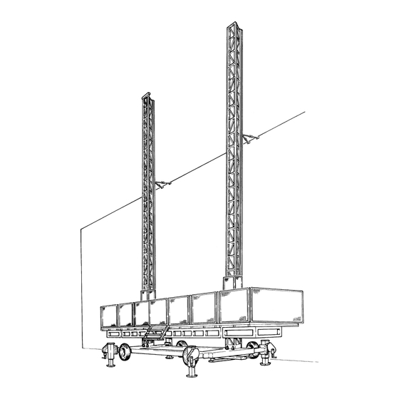
DIN VDE 0185, part II, §5.2 The cable supplied (25 mm² cross section, 25 m long) must be connected to the terminal box on the building site. Fig.6-19 Lightning protection 6-14 MS 3000 • 9095-032A... -
Page 45: Operation
- anchors - presence of all security devices - connection between mast elements - position of the masts - any loose components - ground supports and the quality of the ground - electrical connections MS 3000 • 9095-032A... - Page 46 The display will show code 00. If the electric safety circuit (gates, etc.) is closed the blue light on the control box will burn. Fig.7-2 Emergency push-button MS 3000 • 9095-032A...
-
Page 47: Testing
Release the brake lever. Release the other brake. The platform should not descend. Release the brake lever. If the platform descends, the mast climbing work platform must not be used. Consult the service engineer. Fig.7-3 Brake lever platform MS 3000 • 9095-032A... -
Page 48: Operation From The Platform
Open the trap door in the platform. Each motor is provided with a lever with which the motor brake can be released (A, Fig.7-5). Fig.7-5 Brake lever platform MS 3000 • 9095-032A... - Page 49 The speed of descent will be limited by the centrifugal brake. After a maximum descent of 5 metres, stop the platform for 2 minutes in order to avoid the centrifugal brakes becoming overheated, which will result in their working less efficiently. MS 3000 • 9095-032A...
- Page 50 OPERATION MS 3000 • 9095-032A...
-
Page 51: Disassembly And Transport
Release the brakes and allow the platform to descend onto the buffers (A, Fig 8-1). Disconnect the electrical supplies. Raise the jacks and remove the ground supports. Remove the control box. Fig.8-1 Brake lever platform MS 3000 • 9095-032A... - Page 52 Locking pin outrigger 11. Disassemble the platform extensions. Slide in the outriggers and secure them. 12. Disassemble the platform elements. 13. Slide in the outriggers of the chassis and secure them. Fig.8-3 Locking pin outrigger chassis MS 3000 • 9095-032A...
-
Page 53: Maintenance
During maintenance activities, the emergency stop switch must be activated. Parts must comply with to the technical specification of Hek Manufacturing b.v.! Use only original parts of Hek Manufacturing b.v. 9.2 Maintenance intervals... - Page 54 - Cover the basic machine with a tarpaulin; in every case, cover the control boxes and the limit switches. - Screw out the jack of the chassis so that it does not rest on its wheels. - For long-term storage, consult your dealer. MS 3000 • 9095-032A...
-
Page 55: The Motor Brake
(1). The contact between the friction material on either side of the rotor, the anchor plate and the friction plate results in the required braking effect. MS 3000 • 9095-032A... - Page 56 The air gap "a" is adjusted by the manufacturer to 0.3 mm and must never be more than 1.1 mm. To check: Switch off the mast climbing work platform at the mainswitch and secure the switch with the padlock. MS 3000 • 9095-032A...
- Page 57 "a" is readjusted, as security can be adversely affected. 13. Re-fit the fan and secure it to the shaft. 14. Mount the fan cover and the brake release mechanism. Fig.9-2 Motorbrake MS 3000 • 9095-032A...
- Page 58 MAINTENANCE MS 3000 • 9095-032A...
-
Page 59: Malfunction Analysis
- Switch defective Control voltage - Fuse F104 deactivated - Consult an electrician In all cases not covered by the above malfunction tables an electrician must be consulted. MS 3000 • 9095-032A 10-1... - Page 60 Brake distance too long - Adjust brake Other malfunctions The platform does not develop - Inform your technical service or sufficient power dealer In all cases not covered by the above malfunction tables an electrician must be consulted. 10-2 MS 3000 • 9095-032A...
-
Page 61: Machine Disposal
- Demolition. Discarding the machine - Drain the oil out of the reduction gearbox and dispose of this via an authorized facility. - Remove any usable parts. - Dispose of the remainder via waste disposal facility. MS 3000 • 9095-032A 11-1... - Page 62 MACHINE DISPOSAL 11-2 MS 3000 • 9095-032A...
-
Page 63: List Of Keywords
Platform posts Emergency push-button Platform width 6-12 Emergency situation Plug-in fence EMOS 5-2, 6-14 Power supply socket EMOS program numbers Proximity switch End fence End stop Right Fence posts Foreword Gate Ground pressure Ground support MS 3000 • 9095-032A 12-1... - Page 64 LIST OF KEYWORDS Safety Safety after use Safety features Safety in use Safety prior to use Speed Step Storage Support points Symbols Technical details Testing Transport 4-1, 8-1 Transport weight 12-2 MS 3000 • 9095-032A...
-
Page 65: Appendices
APPENDICES MS 3000 • 9095-032A... - Page 66 APPENDICES MS 3000 • 9095-032A...
Need help?
Do you have a question about the MS 3000 and is the answer not in the manual?
Questions and answers