Table of Contents
Advertisement
Quick Links
Advertisement
Table of Contents

Related Manuals for Rotex GW-20 C22


Summary of Contents for Rotex GW-20 C22
-
Page 2: Table Of Contents
All rights reserved. The information provided applies to the product in its standard version. Rotex Heating Systems GmbH can therefore not be held liable for any damages arising from any specifications of the product which deviate from the standard version. The available information has been compiled with the greatest possible care, but Rotex Heating Systems GmbH can not be held liable for any mistakes in the information, or for any consequences thereof. - Page 3 In case of any doubt, please contact the manufacturer. Keep the installation instructions near the unit. Abbreviations and terms used Description To be referred to as High Efficiency Rotex RKOMB22AAV1H, RKOMB28AAV1H, Unit RKOMB33AAV1H Unit with piping for central heating CH installation System with pipes for domestic hot water...
-
Page 4: Safety Instructions
This product is intended for domestic use only. The manufacturer Rotex Heating Systems GmbH accepts no liability for damage or injury caused by the failure to (strictly) observe the safety instructions, or negligence during the installation of the Rotex RKOMB*AAV1H wall-mounted gas boiler and any associated accessories. -
Page 5: Unit Description
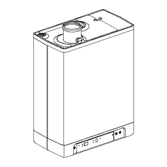
UNIT DESCRIPTION General The Rotex RKOMB*AAV1HAAV1H wall-mounted gas boiler is a closed unit. The unit is intended to provide heat to the water of a CH installation and the domestic hot water installation. The air supply and combustion gas outlet can be connected to the unit by means of two separate pipes. -
Page 6: Operating Modes
Operating modes The operating mode of the unit is indicated by means of a code on the service display of the operating panel. The unit is not in operation, but is connected to the electricity supply. No response is given to requests for domestic hot water or CH water. The unit frost protection is active. This means that the pump will start running and the exchanger will be heated up if the temperature of the water in the system drops too far. -
Page 7: Pc Interface
Tap water operation The hot water supply takes precedence over the heating. If the flow switch senses a request for more than 2 l/min of domestic hot water, any CH requests will be interrupted. After the fan has switched on (code ) and there has been an ignition (code ), the controller will switch to domestic water operation (code... -
Page 8: Frost Protection
2.5.1 Frost protection The unit is fitted with frost protection in order to prevent it from • freezing. If the temperature of the heat exchanger drops too low, the pump will start running until the temperature of the heat exchanger is sufficiently high. -
Page 9: Main Components
MAIN COMPONENTS CH pump Air supply (only when using twin pipe flue system) Gas valve Flue gas/air inlet concentric adapter Burner controller (incl. operating panel) Connection block / terminal strip X4 Sensor S1 (flow) Condensate drain pan Sensor S2 (return) Domestic hot water sensor S3 Siphon Flow sensor... -
Page 10: Accessories
Accessories Description Article numbers B-pack small EKFJS*AA B-pack middle EKFJM*AA B-pack large EKFJL*AA Valve kit EKVK4AA Cover plate EKCP1AA Outdoor sensor EKOSK1AA 3-way valve set EK3WV1AA Flue gas adapter Concentric Ø 80x125 EKHY090717 Flue gas adapter Parallel 80 mm EKHY090707 Propane conversion set *KOMB28AAV1H &... -
Page 11: Installation
INSTALLATION Installation measurements Unit with pipes connected downwards: Unit + wall mounting strip Supply CH G ¾” (ext) Return CH G ¾” (ext) G ½” (int) Tap water cold R ½” Tap water warm R ½” Condense outlet Ø dn25 (flexible) 517mm RKOMB22AAV1H 577mm... - Page 12 Unit connected to B-pack: Unit + B-pack Supply CH G ¾” (ext) Return CH G ¾” (ext) G ½” (int) Tap water cold R ½” Tap water warm R ½” Condense outlet Ø dn25 (flexible) 770mm RKOMB22AAV1H 830mm RKOMB28AAV1H 890mm RKOMB33AAV1H Flue gas outlet/air inlet Ø60/100 (concentric)
-
Page 13: Installation Space
Installation space The unit must be installed against a wall with sufficient load bearing capacity. In case of light wall constructions, there is a risk of resonance noises. Within 1 meter of the unit, there must be a earthed wall plug. In order to prevent the condense outlet from freezing, the unit must be installed in a frost-free room. -
Page 14: Assembly
Assembly The boiler can be hung to the wall using : the wall suspension strip and a the connection kit EKVK4AA • a B-pack including an expension vessel and a connection kit. • 4.3.1 Assembling suspension strip and assembly bracket Make sure the construction of the wall is suitable for hanging the boiler. - Page 15 4.3.3 Assembling the unit Unpack the unit. Check the content of the packaging, which consists of: • Unit (A) • Suspension strip (B) • Siphon+ flexible hose (C) • Installation instructions • Operating instructions • Warranty card Check the unit for any damage: immediately report damages to the supplier. Install the suspension strip.
-
Page 16: Connecting
CONNECTING Connecting CH installation Rinse the CH installation carefully. Fit the supply pipe (A) and return pipe (B) to the connection set. All pipes must be assembled with no electrical current, in order to prevent shocks from the pipes. Existing connections may not be rotated, in order to prevent leakages. The CH installation must be fitted with: A filling/draining tap (A) in the return pipe, immediately underneath the unit. - Page 17 Underfloor heating distributor without pump Connect the underfloor heating system (D) and set the maximum CH supply temperature of the boiler to the design condition. Fit a clamp thermostat (A) onto the supply tube underneath the boiler. The clamp thermostat with blind cap must be set to a maximum supply temperature of 55°C.
- Page 18 5.1.3 Dividing CH installation in groups in case of additional heat sources Operating principle If the room thermostat switches off the boiler because another heat source (wood heater, open fire etc.) heats the room, the other rooms may cool down. This can be resolved by splitting the CH installation into two zones.
-
Page 19: Connecting Dhw Installation
Connecting DHW installation Rinse the installation carefully. If required, assemble an inlet combination. Assemble the cold (D) and warm water pipe (C) to the connection set. Comments If the unit is only used for warm water supply, the heating function can be •... -
Page 20: Connecting Electronically
Connecting electronically CAUTION A socket with safety ground must be no further than 1 meter from the unit. The socket must be easily accessible. When installing the unit in a damp space, a fixed connection is obligatory, by means of an all-pole main switch with a minimum contact gap of 3 mm. -
Page 21: 5.4 Connect Room Thermostat
5.4 Connect room thermostat 5.4.1 Room thermostat on/off 1. Connect the room thermostat (see par. 10.1). 2. If necessary, set the feedback resistance of the room thermostat to 0.1 A. If unsure, measure the electrical current and set it accordingly. The maximum resistance of the thermostat pipe and the room thermostat amounts to a total of 15 Ohm. -
Page 22: Connecting Gas
Undo the appointment of an RF room thermostat to the CH boiler. Press the reset button of the unit for approximately 5 seconds to • access the RF room thermostat menu of the CH boiler. Press the service button 2x. On the display above the button, a •... -
Page 23: Flue And Air Supply Duct
Flue and air supply duct For the installation of the flue and air supply duct material, see the manual included with the materials. Contact the manufacturer of the relevant flue and air supply duct materials for extensive technical information and specific assembly instructions. -
Page 24: Outlet Systems
Outlet systems Please note that not all flue gas configurations described below are permitted in all countries. Therefore observe local regulations prior to installation. The drawings above are a sample and can differ on details. Explanation flue systems Category in accordance to CE A flue that evacuates the products of combustion to the outside of Make sure the air inlet is open the room containing the appliance. -
Page 25: Flue Material
Flue material The following flue materials can be ordered at Rotex. Also visit the website: fluegas.Rotex.eu Art.no. Description EKFGP2978 Wall Terminal Kit PP/GLV 60/100 EKFGP4651 Extension PP/GLV 60/100 x 500mm EKFGP4652 Extension PP/GLV 60/100 x 1000mm EKFGP4660 Elbow PP/GLV 60/100 90°... - Page 26 Art.no. Description EKFGP4678 Chimney Connection 60/100 EKFGP1856 Flex Kit PP Dn.60-80 EKFGP6340 Extension Flex PP 80 L=10 M EKFGP6344 Extension Flex PP 80 L=15 M EKFGP6341 Extension Flex PP 80 L=25 M EKFGP6342 Extension Flex PP 80 L=50 M EKFGP6324 Connector Flex-Flex PP 80 EKFGP4664 Elbow PP/GLV 60/100 30°...
-
Page 27: Connection To A Flue System Without Air Inlet (B23, B33)
Connection to a flue system without air inlet (B23, B33) CAUTION Make sure the boiler room complies to the regulatory • requirements for connecting to a flue system in accordance to B23 or B33 When connection the boiler to a flue system in •... -
Page 28: Connection To A Sealed Flue System
5.10 Connection to a sealed flue system. 5.10.1 Pipe lengths As the resistance of the flue tube and air supply pipes increases, the power of the unit will decrease. The maximum permitted power reduction is 5%. The resistance of the air supply and the combustible gas outlet depends on the length, diameter and all components of the pipe system. - Page 29 5.10.3 Permitted pipe lengths at parallel air supply and flue tube systems Permitted pipe lengths when applying Ø80 mm (total of flue pipe and air intake pipe together). RKOMB22AAV1 100 m 100 m 100 m 100 m 100 m RKOMB28AAV1 85 m 85 m 85 m...
- Page 30 5.10.4 Free in the market available flue gas materials (C63). The properties of the combustion determine the choices for the flue material. The standards EN 1443 and EN 1856-1 provide the necessary information for choosing the flow material by means of a sticker including an identification string. The Identification string contains the following information: CE marking The standard to comply to:...
- Page 31 5.10.5 Securing the flue system IMPORTANT These regulations are typical for both concentric and parallel flue • systems. The flue system must be secured to a solid structure. • The flue system should have a continuous fall back to the boiler (1.5° to •...
- Page 33 5.10.6 Air supply from the facade and a roof outlet with communal exhaust system Unit category: C83 An air supply from the facade and a roof outlet with communal exhaust system is permitted. IMPORTANT • The air supply in the facade must be fitted with an inlet roster (A).
- Page 34 5.10.7 Combined flue gas outlet/air inlet system Unit category : C43 IMPORTANT A roof outlet through a Combination Air Supply combustion gas • outlet system is permitted. For the communal combustion gas outlet hood and air supply • hood, a declaration of no objection or a Gas certificate from the Gastec Gas institute is required.
- Page 35 Unit category : C93 A flue tube system according to C93 (C33) is permitted when using CE approved flue material or the flue material provided by Rotex. The ponts below have to be considered. General Flue outlet in shaft with 60 or 80 mm diameter (rigid or flexible).
-
Page 36: Commissioning The Unit And The Installation
COMMISSIONING THE UNIT AND THE INSTALLATION Filling and air purge of unit and installation 6.1.1 CH system Insert the unit's plug into a socket. The unit may carry out a self-check: (on service display). The unit will then go into the off setting: (on service display) and the CH pressure is shown on the temperature display. -
Page 37: Commissioning The Unit
Commissioning the unit Reading Operating On/off On/off button CH operation or setting maximum CH temperature Tap/CH button, to set the required temperature Tap operation or setting tap temperature - button Required temperature CH or tap water in °C / pressure CH water in bar / malfunction code + button Tap comfort function eco Tap comfort function off / eco / on... -
Page 38: Switching Off The Unit
Switching off the unit CAUTION Drain the unit and the installation, if the mains electricity supply is interrupted and there is a risk of freezing. Remove the plug from the socket. Drain the unit with the filling/draining tap. Drain the installation at the lowest point. Shut the main tap for the water supply from the hot water section. -
Page 39: Setting And Adjustment
SETTING AND ADJUSTMENT The functioning of the unit can be influenced by means of the (parameter) settings in the boiler controller. Part of this can be configured directly via the operating panel, another part can only be adjusted by means of the installers code. Direct via operating panel The following functions can be operated directly. -
Page 40: Parameter Settings Via The Service Code
Parameter settings via the service code The parameters of the boiler controller have been configured in the factory in accordance with the following table. These parameters can only be changed with the service code. Take the following actions to activate the program memory: Press the and the button simultaneously, until a... - Page 41 Minimum rpm CH Settings reach 20 – 50% Minimum capacity modulating CH pump Setting reach 15 to set value par. 3. Minimum rpm hot water Settings reach 20 – 50% Min. leaving water temperature at OT Settings reach 10 – 60°C (OpenTherm) or RF thermostat Reaction OT and RF room thermostat 0= do not respond to hot water request if requested temperature...
-
Page 42: Setting Maximum Ch Power
Setting maximum CH power The maximum CH power is set to 70% in the factory. If more power is required for the CH installation, the maximum CH power can be changed by adjusting the rpm of the fan. See table: Setting CH power. This table shows the relation between the rpm of the fan and the unit power. -
Page 43: Conversion To Different Type Of Gas
Conversion to different type of gas CAUTION Work on gas carrying parts may only be carried out by a certified installer. If a unit is connected to a different type of gas than the one it has been set to by the manufacturer, the gas dosing ring must be replaced. -
Page 44: Setting Gas/Air Regulation
Setting gas/air regulation The CO setting has been set at the factory and does not require any adjustments, in principle. The setting can be checked by measuring the CO percentage in the combustion gases. In case of any disturbance of the setting, the replacement of the gas valve or the conversion to a different type of gas must be checked, and if necessary set in accordance with the following instructions. - Page 45 No adjustments may be made to the gas valve without prior permission from your local Rotex distributor. In Belgium, the gas valve may NOT be adjusted and/or the seal may NOT be removed or broken.
-
Page 46: Malfunctions
Replace boiler controller for the appropriate version. • 29,30 Gas valve controller fault Replace boiler controller. • Only replace faulty parts with the original Rotex parts. Failing to fit or incorrectly fitting the sensors S1 and/or S2 may lead to serious damage. -
Page 47: Other Faults
Other faults 8.3.1 Boiler controller is noisy when igniting Possible causes: Solution: Gas supply pressure too high. The home pressure controller may be faulty. Contact the energy company. Check the ignition pin distance. Incorrect ignition distance. Replace the ignition pin. Gas/air regulation not correctly configured. - Page 48 8.3.4 The power is reduced Possible causes: Solution: At a high level of rpm, the power has decreased Check the unit, siphon and output system for contamination. by more than 5%. Clean unit, siphon and output system. 8.3.5 CH is not reaching correct temperature Possible causes: Solution: Water pressure in installation is too low...
- Page 49 side. 8.3.8 CH installation stays warm unwanted Possible causes: Solution/cause: Check the wiring. Room thermostat/weather dependent regulation Check OpenTherm and On/off connection of the unit. faulty or short circuited. Replace the thermostat. Replace the weather-dependent regulation. Unwanted circulation in the CH circuit due to thermosiphon effect or second pump in CH installation is heated due to Tap comfort.
-
Page 50: Maintenance
MAINTENANCE The unit and the installation must be checked by a certified installer, and cleaned if necessary. CAUTION Work on gas carrying parts may only be carried out by a certified installer. After work, check the flue gas carrying parts for air tightness. If the unit has just been operational, some parts may be hot. - Page 51 9.1.3 Fitting During maintenance the seal front plate needs to be replaced. When assembling, check the other seals for damages, hardening, (hairline) fractures and/or discoloration. Where necessary, place a new seal. Also check the correct positioning. If retarders are not fitted, or incorrectly fitted, it may lead to serious damage.
-
Page 52: Technical Specifications
TECHNICAL SPECIFICATIONS Model name RKOMB22AAV1 H RKOMB28AAV1 H RKOMB33AAV1 H Condensing boiler Low temperature boiler B1 boiler Combination heater Domestic water Nom. load upper value, Qn (Hs) 6,2 – 24,6 7,9 – 31,1 8,0 – 36,3 Nom. load lower value, Qn (Hi) 5,6 –... -
Page 53: Technical Product Fiche In Accordance To Celex-32013R0811
G20 – Natural gas E/H G25 – Natural gas LL/L G31 – Liquefied Propane gas 10.1 Technical Product Fiche in accordance to CELEX-32013R0811 Supplier Rotex Heating Systems GmbH Langewiesenstraße 10 D-74363 Güglingen Type designation RKOMB22AAV1 H RKOMB28AAV1 H RKOMB33AAV1 H... -
Page 54: Electrical Diagram Rkomb22Aav1 H, Rkomb28Aav1 H & Rkomb33Aav1 H
10.2 Electrical diagram RKOMB22AAV1 H, RKOMB28AAV1 H & RKOMB33AAV1 H Earth connection exchanger Fuse (3.15 A T) CH pump DHW sensor Ignition plug Gas block + ignition module Resistance Mass flow sensor Flow temperature C Boiler controller Ignition/ionization pin CH water pressure sensor sensor Return temperature Earth connections... -
Page 55: Ntc Resistances
10.3 NTC resistances NTC 12 kOhm T [°C] R [ohm] T [°C] R [ohm] T [°C] R [ohm] T [°C] R [ohm] 76020 18300 5522 1994 58880 14770 4609 1717 45950 12000 3863 1467 36130 9805 3253 1266 28600 8055 2752 1096 22800... -
Page 56: Warranty Conditions
WARRANTY CONDITIONS The general warranty conditions of Rotex Heating Systems GmbH apply to this product. The warranty is void if it is determined that the faults, damages, or undue wear are attributable to improper use or inexpert treatment or inexpert repair, setting, installation or maintenance, by non-certified installers, or that it was exposed to substances with aggressive chemicals (incl.
Need help?
Do you have a question about the GW-20 C22 and is the answer not in the manual?
Questions and answers