
Related Manuals for Weber Ultrasonics SONIC DIGITAL HS MD

Summary of Contents for Weber Ultrasonics SONIC DIGITAL HS MD
-
Page 1: Operating Instructions
SONIC DIGITAL HS - Ultrasonic Generators Operating Instructions for Ultrasonic Generators of the SONIC DIGITAL HS MD MULTI PURPOSE Art. Nr. 90003403GB Software: 3.10 As per: 29.01.2009 Version: 01... -
Page 2: Table Of Contents
Installation variants of the generator Warranty CE Declaration of Conformity Index Service hotline Spare parts Production, sales and service: Weber Ultrasonics GmbH Phone: +49 (0)72 48 / 92 07-0 Im Hinteracker 7 Fax: +49 (0)72 48 / 92 07-11 76307 Karlsbad-Ittersbach mail@weber-ultrasonics.de Germany www.weber-ultrasonics.de... -
Page 3: Introduction
SONIC DIGITAL HS - Ultrasonic Generators Introduction Dear Customer, Thank you for purchasing this Weber Ultrasonics product. You have chosen a first-class product that was developed using the latest technology. It is vital that you read these operating instructions and follow them carefully before installing or commissioning your product. - Page 4 SONIC DIGITAL HS - Ultrasonic Generators Never operate the device in areas where moisture could penetrate the device. The platform for the device must be sufficiently stable, as severe damage could result if the device is jolted or dropped. Ensure that the power supply specifications given on the device are met. Only converters with the correct frequency, power output and dimensions may be used with this generator.
-
Page 5: Assembly
SONIC DIGITAL HS - Ultrasonic Generators Assembly Notes on the installation location Power supply Connections on the back of the generator Assignment of the 15-pole interface socket Description of the interface - 5 -... -
Page 6: Power Supply
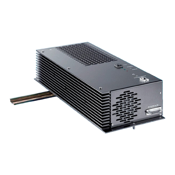
SONIC DIGITAL HS - Ultrasonic Generators Notes on the installation location During operation the generator will become very hot. To ensure that the generator can dissipate this heat well, the generator must be fitted with the fan facing downward. If the generator is to be fitted horizontally, it must be assembled with the cooling profile at the top. Ensure that there is sufficient space for air circulation. -
Page 7: Weber Ultrasonics Gmbh Phone: +49 (0)72 48
Converter negative connection: Shield of the BNC socket Converter positive connection: Inner conductor of the BNC socket Use only the specially provided connection cable from Weber Ultrasonics to connect the converter! ATTENTION: • Only use cables specified by the manufacturer. - Page 8 SONIC DIGITAL HS - Ultrasonic Generators Assignment of the 15-pole interface socket PIN no. on DSUB socket Signal name Description interface +15 VOLT OUT 15 Volt for external use POUT Output 0 – 10 Volt = Power output 0 – 100% P-EXT.-IN Input 5 –...
- Page 9 SONIC DIGITAL HS - Ultrasonic Generators INTERFACE DESCRIPTION 1.) The "+15 Volt Out" signal DSUB pin 1 A voltage of 15V is available at this output. This voltage can be loaded with max. 100 mA and can, for example, be used to output a voltage for the "HF-DA" and/or "Error" functions. This voltage can also be used to switch on the generator on the "FS-24 V"...
- Page 10 SONIC DIGITAL HS - Ultrasonic Generators 8.) The "FS-24 Volt" signal DSUB PIN 13 Activation of the generator (ultrasound on) by the supply of 15 - 24 V between PIN 13 and GND (PIN 4/15) 9.) The "FS-GND" signal DSUB PIN 14 Activation of the generator (ultrasound on) with a relay contact or switch by connecting PIN 14 on the DSUB socket to GND (PIN 4/15).
-
Page 11: Operation
SONIC DIGITAL HS - Ultrasonic Generators Operation Operating and display elements on the front panel Operating and display elements on the external control console The LCD display Functions in the Settings menu - 11 -... - Page 12 SONIC DIGITAL HS - Ultrasonic Generators Operator elements and display of the generator "TEST" button: This button is used to turn on the generator for testing LED-Power: Lights up when the device is correctly supplied with mains voltage. HF LED: Lights up when the generator emits HF voltage Error LED: Lights up in the event of an error...
- Page 13 SONIC DIGITAL HS - Ultrasonic Generators The LCD display Various screens and functions are available in the LCD display: Start screen On the top left is the frequency in Hertz, in the centre the amplitude set in percent (adjustable between 50% and 100%), and on the right the last power output in watts. In the bar graph, the last power output in percent is also shown in diagram form.
- Page 14 SONIC DIGITAL HS - Ultrasonic Generators 5 different welding modes Five different welding modes can be selected via the "Welding" menu item (the welding modes can be deactivated in the Administrator Settings menu and then no longer appear in the menu). If only the Remote Mode is enabled and P-Window and T-Window are not, the "Welding Screen"...
- Page 15 SONIC DIGITAL HS - Ultrasonic Generators Weld by Time If the generator is set to "Weld by Time", you can set a time of 0.01 seconds to 9.99 seconds. The welding process begins when you press the test button or activate the generator via the remote control input.
- Page 16 SONIC DIGITAL HS - Ultrasonic Generators Weld by Peak Power In the "Weld by Peak Power" menu option, you can set a time of up to 9.99 seconds and a power (Watt), that is to be emitted within the set time. If the set power output is not reached within the defined time, the "Timeout"...
- Page 17 SONIC DIGITAL HS - Ultrasonic Generators After Burst In order to clean the sonotrode of residue from the previous welding process, you can again emit energy to the sonotrode here. You can set a delay time before the After Burst of up to 9.99 seconds.
-
Page 18: Functions In The Settings Menu
SONIC DIGITAL HS - Ultrasonic Generators Functions in the Settings menu Control Assignment Here you can set how the generator receives the reference value specifications. Internal Front means with the front control panel (or with the external control console on the Basic version), ext. - Page 19 SONIC DIGITAL HS - Ultrasonic Generators TEST BUTTON Here are three configuration options for the test button on the front plate: PUSH Generator is switched on when the test button is pushed and switched off when the button is released. TOGGLE Generator is switched on when the test button is pushed.
-
Page 20: Functions In The Administrator Settings Menu
SONIC DIGITAL HS - Ultrasonic Generators Functions in the Administrator Settings menu This Administrator Settings menu is only for qualified service personnel. Faulty settings in this menu can irreparably damage the generator or the connected transducer system. The password is only issued to registered administrators and is available from our service contact number. Adjusting the starting frequency The resonant frequency of the connected system must be known. - Page 21 SONIC DIGITAL HS - Ultrasonic Generators If "YES" is selected in "Configure Remote Mode", the "Weld by Remote" welding mode is active in the Operator menu (activation via test button or one of the interface activation signals). If "NO" is selected, this mode is inactive and does not appear. If "YES"...
- Page 22 SONIC DIGITAL HS - Ultrasonic Generators I/O Polarities Remote IN: By changing this value, you can change the polarity of the remote control input. Factory default settings: A closed contact switches the generator on. Symbol "H": When the contact is closed, the generator is switched on Symbol "L": When the contact is open, the generator is switched on Error out:...
- Page 23 SONIC DIGITAL HS - Ultrasonic Generators Pout displayed maximum output In this menu option, you can set the maximum output of the generator shown in the display. Do not change these settings as the equipment has already been configured in our test facility. Temperature This menu item shows the current temperature of the generator.
- Page 24 SONIC DIGITAL HS - Ultrasonic Generators Soft Amplitude With this menu item the soft start can be activated (enabled) or deactivated (disabled). Please read carefully! It is possible that a transducer system does not start up with the required amplitude (e.g. high contact pressure, high transducer system quality, etc.).
- Page 25 SONIC DIGITAL HS - Ultrasonic Generators Example 2: Before starting with the Softstart configuration, note the generator-specific factory settings that are displayed in the I-LIMITS menu item. I min = 50 corresponds to 50 % amplitude (same as factory default setting) I min = 100 corresponds to 100 % amplitude (same as factory default setting) I min to I max in this example are therefore 50 steps (I max –...
- Page 26 SONIC DIGITAL HS - Ultrasonic Generators TEST BUTTON There are three configuration options for the test button on the front panel: PUSH Generator is switched on when the test button is pushed and switched off when the button is released. TOGGLE Generator is switched on when the test button is pushed and switched on when the button is released.
-
Page 27: Error Messages And Troubleshooting
SONIC DIGITAL HS - Ultrasonic Generators Error messages and troubleshooting The following error messages may appear on the display: A – PROTECTION ACTIVE The electronic overcurrent fuse has detected an error Possible causes: • Transducer defective • Supply cable or connector defective Remedy: •... -
Page 28: Maintenance
SONIC DIGITAL HS - Ultrasonic Generators Maintenance The ultrasonic generator does not require any special maintenance. Dust and dirt should be removed regularly using a damp cloth. IMPORTANT: • Do not use aggressive cleaning agents! • Do not clean using ultrasound! Specifications SONIC DIGITAL LC MD Device specifications of all generators... -
Page 29: Warranty
CE Declaration of Conformity Weber Ultrasonics GmbH, hereby declare under sole responsibility that the product: Designation: Ultrasonic generator „HS xxxx MD“incl. transducer system by Weber Ultrasonics (xxxx stands for the various outputs) complies with the requirements of the following EMC standards: EN 50081-1... -
Page 30: Index
SONIC DIGITAL HS - Ultrasonic Generators Index Administrator Settings Holding Settings 18, 20 After burst Safety instructions Assembly Soft Amplitude 24, 25 Assignment of the interface socket 8 Interface Spare parts Assignment of the mains connection 8 Installation 3, 6 Specifications Installation site 3, 6...
Need help?
Do you have a question about the SONIC DIGITAL HS MD and is the answer not in the manual?
Questions and answers