Table of Contents
Advertisement
Advertisement
Table of Contents

Related Manuals for gfm GF-Primo Dolly

Summary of Contents for gfm GF-Primo Dolly
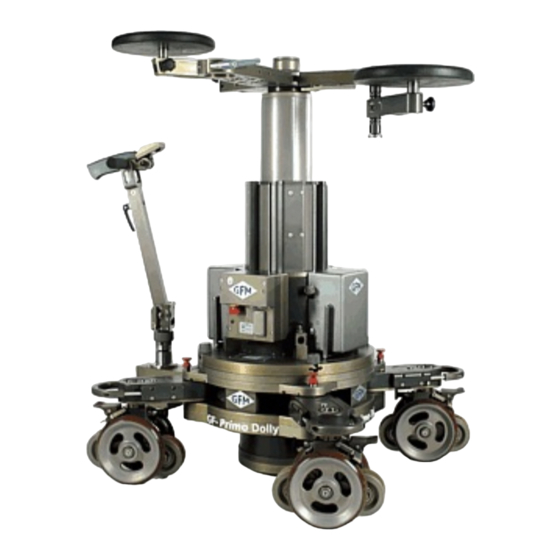
- Page 1 Instruction Manual and Safety Guidelines GF-Primo Dolly GF-Secondo Dolly Valid: November 2015 Grip Factory Munich GmbH Tel.: +49 (0) 89 319 0 129-0 Fürholzener Straße 1 Fax: +49 (0) 89 319 0 129-9 85386 Eching bei München e-mail: info@g-f-m.net Germany...
-
Page 2: Table Of Contents
Holders for the HCU 3.5.1 HCU Holder on the Steering Handle 3.5.2 HCU Holder on the Column: Selecting Steering modes: 3.6.1 GF-Primo Dolly Steering modes: 3.6.2 GF-Secondo Dolly Steering modes: Combi-Wheels – GF-Primo & GF-Secondo: 3.7.1 Combi-wheel Brake 3.7.2 Disconnecting the wheels from the steering: 3.7.3... - Page 3 CALIBRATING THE COLUMN 10.1 Calibration procedure 10.1.1 Calibrating the column in cable mode 10.1.2 Calibrating the column in wireless mode OPERATING THE HAND CONTROL UNIT (HCU) 11.1 HCU Settings 11.1.1 Explanation of the menu points 11.1.1.1 Sub-menu point USER 11.1.1.2 Sub-menu point DISPLAY 11.1.1.3 Sub-menu INFO...
-
Page 4: Safety Guidelines To Operate The Dolly
Ensure that the underlay meets the specified support and stability requirements. Only GFM Track or comparable track systems with a payload capacity of 1200kg / 2640lbs and a maximum track runner distance of 640mm / 25inches (measured inside edge to inside edge) may be used. - Page 5 Dolly accessories: For safety reasons only original accessories manufactured by GFM may be used with the dolly. Procedure in case of accident or damage: In case of accidents caused by disregarding the manufacturer’s instruction manual or due to other...
- Page 6 General guidelines for dolly transport: Attention: To avoid damage to the equipment or persons we recommend using the GFM customized transport cases and to ensure that these are strapped down correctly during transportation to avoid any unwanted moving or collisions. Furthermore, all 4 combi-wheel brakes must be locked to avoid unwanted movement of the GF-Primo or GF-Secondo Dollies during transportation.
-
Page 7: Technical Specs For Gf-Primo - / Gf-Secondo Dolly
2 Technical Specs for GF-Primo - / GF-Secondo Dolly The difference between the GF-Primo - and GF-Secondo Dolly is effectively the different base dollies. The columns are identical. The GF-Primo Base has a central "one touch" selector allowing for immediate, one handed, switch over to crab, front or rear wheel steering. - Page 8 2,5 sec Duration of column lift 2,5 sec 0 – 70cm / 0 – 27,6“ 0 – 70cm / 0 – 27,6“ Lift range 140cm / 55,1“ Maximin column height 142cm / 55,9“ 70cm 27,6“ Minimum column height 72cm 28,3“ 250kg / 551lbs Maximum column lift capacity 250kg / 551lbs...
-
Page 9: The Gf-Primo Dolly
3 The GF-Primo Dolly Changing the batteries The dolly’s batteries are connected to the column with a user friendly “drop & go” system. The column requires 2 x 24Volt Battery units to function. Centre the battery over the locking mount. Move the battery into position and drop it gently onto the locking shaft. - Page 10 The carry handle double functions as a lock for the platforms. Extend the handle by pressing the stainless steel button on the left side of the wheel arm. At the same time pull the handle out. Attach the required number of platforms. To secure them, press the stainless steel button and push the handle towards...
-
Page 11: Mounting The Hi/Low Platform System
3.2.2 Mounting the Hi/Low Platform System: The 2 part Multifunctional Hi/low Platform can be dismantled by unscrewing 2 bolts, allowing the wider platform part to be mounted on the base dolly as described on the previous page Remove the 2 locking bolts to dismantle the platform... -
Page 12: Mounting The Hi/Lo Platform For Use On Track
3.2.3 Mounting the Hi/Lo Platform for use on track: The Hi/Low Platform can be used on track in conjunction with GFM Skateboard or Track Wheels. Attention: Use with track and skateboard wheels is only possible with straight track. To use the Hi/Low Platform on curved track the either remove the wheels or adjust the height so the wheels are not in contact with the curved track. - Page 13 Connect the Skateboard Wheels by pulling back the safety pin and fitting the wheel to the mounting shaft. Undo the safety Ensure the safety pin is inserted Connect the track wheels on both sides of platform Absenken der Plattform auf die Schienen Unlock the grey locking handle to allow height...
-
Page 14: Wheel Arm Adjustment
Wheel arm adjustment: Each of the 4 wheel arms has an individual locking mechanism to secure the position of the wheel arms and ensure a stable, no-play base. To adjust the wheel arms to change from, for example, standard to narrow gauge note the following. Pull to open position Hold the locking pin in the released... -
Page 15: The Steering Handle
The Steering Handle 3.4.1 Connectiong the Steering Handle The Steering Handle can be attached to each of the 4 wheel arms on the GF- Secondo as well as the central steering gearbox on the GF-Primo. Insert the steering 5 steering positions. handle into one of the 5 steering positions. -
Page 16: Holders For The Hcu
To adjust the length of the steering handle, open the release handle and adjust to required height. When the steering handle is in position, close the release handle. Holders for the HCU 3.5.1 HCU Holder on the Steering Handle Pull back the Push the HCU locking pin and down so it fits... -
Page 17: Selecting Steering Modes
Selecting Steering modes: 3.6.1 GF-Primo Dolly Steering modes: To change from one steering mode to another first of all ensure that all 4 Combi- wheels are pointing in a straight line as seen from the rear of the dolly In each of the 4 steering rod mounts you will see 2 notches machined into each rim. - Page 18 GF-Primo‘s 3 steering modes and selector position:...
-
Page 19: Gf-Secondo Dolly Steering Modes
3.6.2 GF-Secondo Dolly Steering modes: Each of the 4 combi-wheels has an individual selector switch which enables each wheel to be fixed, connected or disconnected from the steering mechanism: Switch position SP 1 Combi-wheel in fixed position Switch position SP 2 Combi-wheel steerable Switch position SP 3 ... - Page 20 GF-Secondo’s three steering modes and their selector positions:...
-
Page 21: Combi-Wheels - Gf-Primo & Gf-Secondo
Combi-Wheels – GF-Primo & GF-Secondo: 3.7.1 Combi-wheel Brake Each Combi-wheel has a kick down brake for the studio /pneumatic wheels. The 2 Combi-wheels at the rear of the dolly also have integrated track wheel brakes attached to the standard wheel brake. Kick down to lock the Studio &... -
Page 22: Disconnecting The Gf-Secondo Combi-Wheel From The Steering And Removing The Combi-Wheel Unit
3.7.3 Disconnecting the GF-Secondo Combi-wheel from the steering and removing the Combi-wheel unit Selector switch pointing downwards: Disconnected from steering = wheel rotates freely i.e. on Position SP3 Locking pin to remove Combi- wheel To remove the GF-Secondo Combi-wheels from the Base-Dolly set the selector switch at position SP3. Then pull the Locking Pin to remove the wheel unit by moving it downwards. -
Page 23: Going On Track
Going on Track: When driving onto track using a drive ramp, ensure that the track wheel brakes on the Combi-wheels are at the rear of the wheel as it goes onto the track. If not the brake will engage and stop the dolly from moving. - Page 24 Turnstile Brake: Push towards centre to open, pull towards seat to lock. Collision protection: Seat arm moves upwards in the event of a collision. Seat adjustment: Pull towards seat to open. Push towards centre to lock.
-
Page 25: Removing The Column With The Carry Bars
3.10 Removing the Column with the Carry Bars: Insert the 4 carry bars ensuring that the locking pin are engaged fully. Open the 4 column locking nuts and tilt them back. Remove the column carefully by lifting. 2 persons! To remove the carry bars release the locking pin and pull out. -
Page 26: Hand Control Unit Components
4 Hand Control Unit Components The following describes the individual button functions and components on the Hand Cotrol Unit. On/Off (emergency Off button) Status-LED Radio signal sender Display RMP-Button SPD-Buton MARK / LIMIT-Button Rocker Switch Programm and Mode Selector Button Cover SD-card SD-card socket Cover Mini-USB plug... - Page 27 Handle Rosette Exchangeable HCU cover Battery cover HCU battery Battery cover lock...
-
Page 28: Electronic Unit Components
5 Electronic Unit Components The following describes the electronic components: On- / Off-Switch with Status-LED Connector for Hand Control Cable Emergency Off Switch! Press to deactivate electronic! Must be extended to allow operation!! External antenne Serial number Cover for Back Up Drive System with Channel display 6 Before operating the HCU and the Dolly When the dolly arrives from the factory the HCU and electronic unit will already be paired and set up to... -
Page 29: Activating The Hcu And The Dolly
7 Activating the HCU and the Dolly The GF-Primo and GF-Secondo Dolly can be operated via cable or in wireless mode. Activating wirelss mode To operate the dolly in wireless mode proceed as follows: Attention: The Dolly only functions if the HCU and electronic unit are paired. As soon as either unit is replaced it must be paired with the other unit. -
Page 30: Activating In Cable Mode
Display red Display off Display blue (ready) Attention: When the HCU is switched off, the electronic is also automatically switched off. To switch on again, repeat the above (first switch on the electronic then the HCU. As soon as both units are activated, operation can proceed. Activating in cable mode To operate the dolly in cable mode proceed as follows: Connect the HCU and electronic unit with the delivered HCU cable by inserting the connectors... -
Page 31: Synchronising The Wireless Channels
Info: Shortly after switching on, the LED on the electronic will blink alternatively from red/green. The HCU Display and the LED on the HCU will show up in red. After approx.. 2 seconds both LEDs will show green and the HCU display will alight in blue. Display off Display red Display blue (ready) - Page 32 Cable connection Dolly - Marking Fischer Plug As a reference use the alignment markings on the „Fischer“ Tip: Connectors to insert correctly Activate the dolly by pressing the on/off button on the HCU. Info: Shortly after switching on, the LED on the electronic will blink alternatively from red/green.
-
Page 33: Synchronising The Channels In Wireless Mode
Synchronising the channels in wireless mode Activate the electronic unit and the current channel number will be shown as follows: LED red LED off LED green / red blinking (ready) Now switch on the HCU. To change the channel enter the following key combination: Press and hold the RMP button. - Page 34 Key combination to change the channel Change the channel...
-
Page 35: Pairing The Hcu And Electronic Unit
9 Pairing the HCU and Electronic unit Pairing via cable: To operate the dolly in wireless mode the electronic and the HCU must be paired. This will be pre-set by the factory when the dolly is first delivered. If however, the units are not matching because, perhaps, a replacement HCU is used it is essential to pair both units to each other. -
Page 36: Pairing In Wirelss Mode
Info: Shortly after switching on, the LED on the electronic will blink alternatively from red/green. The HCU Display and the LED on the HCU will show up in red. After approx.. 2 seconds both LEDs will show green and the HCU display will alight in blue. -
Page 38: Calibrating The Column
10 Calibrating the column When and why the column may require calibration The column will need to be calibrated: After a service or repair After a software update After the column is crashed / driven against an object / hit the mechanical top or bottom of column lift range After using emergency switch Why the column must be calibrated:... -
Page 39: Calibration Procedure
10.1 Calibration procedure The column may be calibrated in cable or wireless mode 10.1.1 Calibrating the column in cable mode Proceed as follows Attention: During calibration the column must not be loaded. Calibrate only when there is not equipment mounted on the column! Attention: During calibration the columns lift range will be driven through and set. - Page 40 Press and hold the SPD-button, then switch the column on by pressing the ON/OFF button on the HCU whilst holding the SPD button pressed. Info: In cable mode the column is switched on from the HCU. As soon as the HCU LED is on the SPD-button can be released. The Display shows „CAL DOLLY“.
-
Page 41: Calibrating The Column In Wireless Mode
10.1.2 Calibrating the column in wireless mode The column may be calibrated in wireless mode Proceed as follows Attention: During calibration the column must not be loaded. Calibrate only when there is not equipment mounted on the column! Attention: During calibration the columns lift range will be driven through and set. The column will drive slowly to the bottom position and then to the top position and finally return to the starting position. - Page 42 Tastenkombination zum Kalibrieren des Dolly...
-
Page 43: Operating The Hand Control Unit (Hcu)
11 Operating the Hand Control Unit (HCU) The following explains how to use the HCU. Info: The HCU can only be used when switched on and when paired with the respective dolly / electronic! 11.1 HCU Settings The HCU display shows you various settings and provides information such as the following: User settings for individual operators or changing from settings Display settings such as brightness, contrast, selecting column movement in mm or imperial Information about the Dolly... -
Page 44: Explanation Of The Menu Points
11.1.1 Explanation of the menu points 11.1.1.1 Sub-menu point USER Scroll to the menu point USER and confirm by pressing ENTER to activate the sub-menu SEL USER (Select USER). Menu selection USER There are 4 USER‘s to choose from. Each USER can individualise settings such as LIMIT and MARKER as well as Ramps and Speeds. -
Page 45: Sub-Menu Point Display
11.1.1.2 Sub-menu point DISPLAY Use the Rocker Switch to select DISPLAY and confirm by pressing. Now it is possible to select the preferred contrast, brightness of the display on the HCU and electronic as well as setting measurements to percentage, metric or imperial. Measuring units: The columns travel may be measured in: IMPERIAL... - Page 46 Setting the display’s contrast and brightness: In the sub-menu CONTRAST or BRIGHTNESS the settings can be changed. Proceed as follows: Using the Rocker Switch, select the sub-menu point CONTRAST or BRIGHTNESS and confirm by pressing ENTER. By pressing the Rocker Switch up or down the intensity of the displays contrast or brightness can be adjusted, Confirm by pressing ENTER.
-
Page 47: Sub-Menu Info
Setting the brightness of the electronics display: The brightness of the display on the electronic can be set in sub-menu DOLLY DIMM. Proceed as follows: Using the Rocker Switch, select the sub-menu point DOLLY DIMM and confirm by pressing ENTER. By pressing the Rocker Switch up or down the intensity of the displays brightness can be adjusted, Confirm by pressing ENTER. - Page 48 Using the Rocker Switch, select the sub-menu point SOFTWARE and confirm by pressing ENTER. The current HCU and electronic software version will be shown. Return to NORMAL mode by pressing the ENTER button and backtracking through the menus. WORK- / RUNTIME: WORKTIME is the time the dolly has been switched on and RUNTIME is the duration the column has been driven / moved.
-
Page 49: Sub-Menu Point Jib On / Jib Off
Wireless signal (RF POWER) RF POWER or signal strength can be adjusted from range 1 (normal distance or mild signal strength) up to step 4 (for longer distance or strong signal strength). We recommend step 1 or 2. To adjust or set the RF Power proceed as follows: Using the Rocker Switch, select the sub-menu point RF Power and confirm by pressing ENTER. -
Page 50: General Hcu Functions
11.2 General HCU functions The following describes general functions such as selecting various speed and ramp settings. 11.2.1 Setting Ramps RMP and Speed SPD A Ramp is the strength of acceleration and deceleration of column when starting or ending a movement. -
Page 51: Special Hcu Modes
11.3 Special HCU Modes Via the HCU it is possible the select different dolly modes which allow a range of operational features: LIMIT: restricts the columns lift range MARKER: selected positions where the column will stop moving RECORD: movement storage PLAY: repeat of stored movement DELETE: cancel / delete position or stored movement The functions can be found in various operation modes and can be explained as follows:... -
Page 52: Extended Modes "Play", "Record" And "Delete
11.3.1.2 Extended Modes “PLAY”, “RECORD” and “DELETE”: These modes are available with an SD card only. “PLAY” Mode: “RECORD”-Mode: “DELETE”-Mode: Recorded movement can be A move can be recorded and Recorded movement can be selected and repeated / stored, Variable Ramps and deleted. -
Page 53: To Change Modes
11.3.2 To change Modes To change from one Mode to the other proceed as follows: Info: After switching on the HCU, it will revert back to the previously selected mode. Switch on the dolly (either in wireless or cable mode). On the underside of the HCU is the HCU Mode Selector Button. -
Page 54: Hcu Modes And The Respective Display
11.4 HCU Modes and the respective Display The software allows for a range of modes to be selected indicating various settings and providing specific information on the display. 11.4.1 NORMAL Mode Offers standard movement with a selection of speeds and ramps. Lower and upper limits can be set. (For setting RMP and SPD see „11.2.1). - Page 55 Explanation of the information shown on the Display: Selected User: The HCU can store 4 different USERS U1, U2, U3, U4. Each USER can set their individual RMP, SPD, Limits as well as Markers for repeated usage. (Setting Limits see „11.4.1.1)“; setting Markers see „11.4.1.2.1“).
- Page 56 Motor temperature: The motor temperature is also shown on the display. It should be noted the temperature shown is that of the outside of the motor in its isolated housing and not the ambient air temperature Note: A safety guard is installed to protect the motor from thermal overload: If, during operation, the motor temperature exceeds 55°C the HCU display will flash red and the temperature digits will also blink.
-
Page 57: Setting Individually Adjustable Limits
11.4.1.1 Setting individually adjustable LIMITs LIMIT mode allows the columns lift range to be reset. The standard range from 0 bis 705 mm can be restricted to e.g. 200 to 500 mm. Proceed as follows: Position the column at the new lower position of e.g. 200 by using the Rocker Switch. It’s easier to reach the required position when using a low speed. -
Page 58: Enter Mode
11.4.1.2 ENTER Mode Entering, editing, deleting and replacing 6 Markers. Setting up the shot Im ENTER Mode enables the storage of 6 positions / MARKERS, or their cancellation or editing. ENTER Mode shows up differently on the display to NORMAL Mode: With the SET-button (in NORMAL Mode RMP) MARKERs can be set With the CLR-button (in NORMAL Mode SPD) set MARKERs can deleted with the MARK-button (in NORMAL Modus LIMIT) already set MARKERs can be selected... -
Page 59: Setting Individually Adjustable Markers
Explanation of the individual display symbols: Currently selected or next MARKER: Shows the MARKERs that can currently be set, over written or deleted. Already set MARKER: Shows already set MARKERs that can be over written or deleted and are indicated beside the Vertical Bar display. - Page 60 MARKERs 3 to 6 can be selected in the same manner. Setting MARKERs...
- Page 61 Over writing MARKERs: Already set MARKERs can be over written as follows: By pressing the MARK-Button, select the MARKER number you want to over write e.g. MARK 1 (Height 400 mm) By using the Rocker Switch drive the column to the new required height e.g. 300mm Now press the SET-Button to reset the MARKER 1 from 400mm to 300mm.
- Page 62 Setting MARKERs in a non-numerical order: Markers must not necessarily be set in a numerical order: Press the MARK-key until the required MARKER shows on the display as the currently selected MARKER. Using the Rocker Switch, drive the column to the required height. Now press the SET-button, to allocate the selected number as the specific MARKER.
- Page 63 Deleting MARKERs: To delete set MARKERs proceed as follows: By pressing the MARK button, scroll to the MARKER that will be deleted, e.g. MARKER 4. To delete the selected MARKER press the CLR-button. Deleteing MARKERs Info: The deleted MARKER position must not necessarily be repositioned as the software recognizes that there is a digit missing and during the movement will show the next available MARKER.
-
Page 64: Marker Mode
11.4.1.3 MARKER Mode In Marker Mode it is possible to activate the recorded MARKERS. Between each MARKER it is possible to vary direction, speed, and alter the ramp. Upon reaching each of the 6 MARKERS the column will stop automatically. Set MARKERs MARK-Button to select required MARKER... - Page 65 After recording the required MARKERs in E-Mode switch to M Mode by pressing the Program and Mode Selector Button on the underside of the HCU. Settings such as Speed and Ramp are accessible and even different Speeds and Ramps can be selected between the various positions.
-
Page 66: Mode Play, Record And Delete
11.4.1.4 Mode PLAY, RECORD and DELETE To access the Mode’s PLAY, RECORD and DELETE an SD-Card is required. Inserting the SD-card To insert the card proceed as follows: Remove the CS card cover Insert the card fully until it clicks into position. Replace the cover. -
Page 67: Record Mode - Recording A Movement Sequence
11.4.1.4.1 RECORD Mode – Recording a movement sequence Attention: Before recording, ensure that the complete liftrange of the column is clear from obstructions. Proceed as follows: In NORMAL Mode, set the required RMP and SPD and move the column to the required position e.g. - Page 68 Recording a sequence...
-
Page 69: Play Mode - Abspielen Einer Gespeicherten Fahrtsequenz
11.4.1.4.2 PLAY Mode - Abspielen einer gespeicherten Fahrtsequenz Attention: Before replaying a recorded sequence, ensure that the complete lift range of the column is clear from obstructions. Proceed as follows: Change to PLAY mode by pressing the mode selector button on the underneath of the HCU. If you have more than 1 sequence recorded scroll to the required file with the Rocker Switch and press the OPEN button to select the file. -
Page 71: Delete Mode - Deleting A Recorded Sequence
11.4.1.4.3 DELETE Mode – Deleting a recorded sequence To delete a recorded sequence, proceed as follows: Change to DELETE mode by pressing the mode selector button on the underneath of the HCU. Scroll to the required file with the Rocker Switch e.g. „MOVE0000“ then press the DEL button If you have more than 1 sequence recorded repeat these steps. -
Page 72: Emergency Operation Of The Column
12 Emergency Operation of the Column The GF-Primo and GF-Secondo Dolly’s electronic is equipped with a back-up systems to enable movement of the column in an emergency situation. Emergency situations are: Defective or non-functioning electronic (HCU cannot operate the electronic) Defective or lost HCU Attention: Emergency operation is not for working with! Using the column with a under load with... -
Page 73: Trouble Shooting
Pins Connector 13 Trouble Shooting The following describes some possible errors and the solutions to correct the errors. Error: Dolly and HCU are not functioning in wireless mode Solution: Check Are the HCU and column equipped with wireless modules? Is the emergency OFF Switch inserted into the off position? If so, twist clockwise to deactivate. - Page 74 If the above solutions do not result in an improvement of the columns performance please service the column (see “servicing the column”). Error: Disturbance of movement during cable operation. Solution: Check the battery voltage with a loaded column whilst moving up and down. Should the voltage fall below 19V replace or charge the batteries.
- Page 75 the HCU battery is in place. The wireless mode does not work without battery. both the HCU and electronic are sending and receiving on the same channel. Before operating the column and the HCU for the first time it is necessary to synchronize both units. Cable mode: Check if the emergency OFF Switch is inserted into the off position.
- Page 76 Error: The calibration mode disrupts by itself during the procedure: Solution: Change from cable to wireless mode or vice versa, then try again. Error: Upon switching on the column an incorrect height is shown! Solution: Calibrate the column. If this doesn’t solve the problem and the error is still present, repeat the procedure. Error: Display is red: Solution:...
-
Page 77: Assembling The Gf-Primo Jib
14 Assembling the GF-Primo Jib Attention: Crushing hazard when assembling the GF-Primo Jib Arm! Rear section and High / Low Rig Middle section Parallelogram rod Connector counter- Platform weights Connection rod Attention: Before you start assembly of the GF-Primo Jib, drive the column to a height of 50mm! Place the middle section of the GF-Primo Jib on to the column’s Euro-adapter. - Page 78 Fit the connection rod onto the steel pin and hand tighten the locking bolt. Connect the connection rod to the connection fork by inserting fully and securing with the locking pin Attention: Before proceeding with the assembly of the GF-Primo Jib, drive the column to a height of 305mm! Connect the rear section to the middle section by sliding the female flange onto the male flange.
- Page 79 Attach the weight triangle to the rear of the arm by aligning the hole for the weight rod over the respective hole on the rear arm and inserting the weight rod. Ensure that the weight rod is the same length on both sides.
- Page 80 The front plate of the jib has 4 threaded holes where the mounting bolt is inserted depending on which platform position is required. E.g. for low position. Screw the mounting bolt into the lower hole. The High/Low Rig has a key link where the mounting bolt must connect to.
- Page 81 The front plate of the Hi / Low Rig has 2 threaded holes where the mounting bolt is inserted depending on which platform position is required. E.g. for low position. Screw the mounting bolt The Platform has a key link where the into the lower mounting bolt must connect to.
- Page 82 Connect the Secure the High / Low Rig High/Low Rig by by pressing it to inserting the the front plate locking bolt and and allowing the screwing it into key link to slide the mounting 14.1 onto the plate. mounting bolt Tighten securely with the locking lever.
-
Page 83: Individual Gf-Primo Jib Components
Individual GF-Primo Jib components Component Weight Platform 16,6 / 36,6 High / Low Rig 15,4 Middle section Rear section + Parallelogram rod 21,5 Connector for weights / 16,5 Connection rod Total weight 82,9 / 182,3 Rear section and High / Low Rig Middle section Parallelogram rod Connector... -
Page 84: Gf-Primo Jib Set-Up Configurations
14.2 GF-Primo Jib set-up configurations Set-up with High/Low Rig The maximum payload on the Platform is limited to 200kg / 440lbs... - Page 85 Attention: Before assembling or operating the GF-Primo Jib ensure that the “Jib On” operational mode is selected and that the HCU display is showing “Jib On”. (siehe 11.2). Set-up without High/Low Rig The maximum payload on the Platform is limited to 250kg / 550lbs Attention: Before assembling or operating the GF-Primo Jib ensure that the “Jib On”...
-
Page 86: Selecting The "Jib On" Mode On The Hand Control Unit
Selecting the “Jib On” mode on the Hand Control Unit 14.3 In this mode, selected Ramps and Speeds are pre-set to ensure a safe Jib arm operation with the GF-Primo Jib. Attention: Operating the GF-Primo Jib on the GF-Primo- or GF-Secondo Dolly is only allowed in „Jib-On“... -
Page 87: Operational Guidelines For The Gf-Primo Jib
14.4 Operational Guidelines for the GF-Primo Jib When operating the GF-Primo Jib observe the following guidelines as well as the guidelines on page 3 & 5: 1. Know the precise weight that will be placed on the platform i.e. person, camera and accessories. -
Page 89: Service
15 Service In general, maintenance should always be performed by qualified personnel in accordance with relevant accident prevention regulations and generally accepted safety rules. Recommended maintenance interval: 1 year We recommend the owner / operator to a visual and functional test of the components listed below several times a year, to make sure that the dolly system is in good condition. - Page 90 / jib arm. Attention: For safety reasons only original spare parts manufactured by GFM may be used for the maintenance or repair. Technical specifications subject to change without notice!
-
Page 91: Regular Inspections
A minimum of 3 years experience in construction design, assembly or maintenance of safety relevant and technical facilities. It is recommended that the safety inspections be carried out by GFM or a local recognized expert. Contact details of domestic and foreign technical experts can be obtained from recognized... -
Page 92: Ec Declaration Of Conformity
17 EC Declaration of Conformity The company: Grip Factory Munich GmbH Fürholzener Str. 1 D-85386 Eching Germany declares, that the • Camera dolly sytem Type: GF-Primo / Secondo Serial no. See type plate Built: See type plate • GF-Primo Jib (where applicable) Serial no.
Need help?
Do you have a question about the GF-Primo Dolly and is the answer not in the manual?
Questions and answers
Hard were error