Advertisement
Quick Links
100 Watts of Output Power at Less than 1% THD from
35
Hz to 20 kHz
Transformer-Isolated Outputs for
for 25V and 70.7V Distribution Systems
Switchable Highpass Filter Protects Driver Loudspeaker
from Excessive Low-Frequency Power Demands
Exclusive Active Dissipation Sensing Circuit Protects
Output Transistors
AC
or Battery Operation
.
.
.
NOTICE
Read this manual before operating
the AI-TEC 15948 Power Amplifier.
. .
FEATURES
Automatic Transfer to Battery Operat~on if AC Power
Fails
and 16 Ohms and
Low Power Consumption
Low Heat Generation
Hinged Front Panel for Easy'Maintenance
Small Size
Light Weight
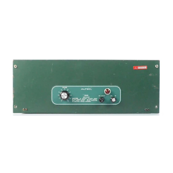
POWER AMPLIFIER
OPERATING
INSTRUCTIONS
Advertisement

Summary of Contents for Altec 1594B
- Page 1 POWER AMPLIFIER OPERATING INSTRUCTIONS NOTICE Read this manual before operating the AI-TEC 15948 Power Amplifier. FEATURES 100 Watts of Output Power at Less than 1% THD from Automatic Transfer to Battery Operat~on if AC Power Hz to 20 kHz Fails Transformer-Isolated Outputs for and 16 Ohms and Low Power Consumption...
-
Page 2: Specifications
DATA CONTENTS Page Graphics Page SPECIFICATIONS Figure 1. Typical Power Output Versus Fre- quency for 0.5% THD and 1% THD DESCRIPTION (8-Ohm Load) Figure Typical Frequency Response Characteristics INSTALLATION Figure 3. Typical % THD Versus Frequency RACK INSTALLATION for 100-Watt Output SHELF INSTALLATION VENTILATION Figure 4. - Page 3 Up t o 5 5 ' ~ (131°F) ambient Dimensions Weight: 35 pounds, ounces Color: ALTEC green ALTEC 15095A Line Transformer Accessories: ALTEC 15335A Line Transformer ALTEC 42526 Shelf Mount Cover ACCESSORIES MUST BE ORDERED Figure Typical % THD Versus Wattage Output at 1000 SEPARATELY...
- Page 4 sturdy enough t o support lightweight equipment placed on DESCRIPTION Four polyethylene feet prevent marring of sur- The A L T E C 15948 Power Amplifier delivers u p t o faces. The A L T E C green finish matches the front panel o f the 15948.
- Page 5 must be ventilated to prevent an excessive temperalure rise. 1 t o 2 and 3 to on TB3). The power input nameplate, Because transistors are heat sensitive, the 15948 should not adjacent to the power cord on the chassis, i s mounted t o be placed adjacent t o heat-generating equipment or in areas show the appropriate side specifying the connections (see where ambient temperature exceeds 5 5 ' ~ ( 1 3 1 ' ~ ) .
- Page 6 For transformer-isolated input, a plug-in 15095A or 15335A Line Transformer must be plugged into receptacle J1 (see Figure 6). The input leads connected t o terminals 3 and 4 of the INPUT terminal board. When shipped from the factory, pins 3 and 4 of J1 are strapped together t o provide 600-ohm input.
- Page 7 Step 3. chassis interior. R137 fully clockwise (see Figure I f the ALTEC 42526 Shelf Mount Cover accessory is in- Turn on power and allow a 5-minute warmup stalled, remove by reversing the steps of the cover installa- Step 4.
- Page 8 Step Adjust R136 and R137 by one of the following Step 4. Carefully insert new or repaired power driver methods [method (a) i s preferred] : PCB into connector. Do not warp, bend or twist the board or conductor may fracture. Locate wire attached to terminal 1 of output transformer T2.
- Page 9 and 3 show normal function, connect Step 4. I f Steps I f component is faulty or damaged, clip leads close to ohmmeter leads to collector and emitter. Read component and then unsolder leads from board. With- on lowest ohms scale. Reverse leads and read draw leads from component side.
- Page 10 :I; I I > ? POWER DRIVE? PCB ASSEI'.'BLY ( A l ! , t i I ' ! I N LOWERED POSITION 1 1 3 Figure Component Locations Inside Main Chassis VOLTAGE RATING PLATE Figure 11. Component Locations on Rear of Chassis...
- Page 13 PARTS Reference Ordering Name and Reference Ordering Name and Designator Number Designator Number Description 27-01-042843-04 PCB Assembly, Power Driver Transistor, 2N5305, selected Transistor, 2N2712, selected Transistor, 2N3906. selected Transistor, 2N5308, low noise, selected Cap.. 7000 pF, 40V 48-03-107447-02 Transistor. 2N5320, 400V Pot., 1 5 K a 220% Cap., 220 pF +lo%,...
- Page 14 PARTS LIST (continued) Reference Reference Ordering Name and Designator Number Description Designator Number Description R113 47 11-102177-01 Res., 15KC?,+10%, Res., 47Q 1 /4W 47-01-102155.01 114W R115.117 Pot., 5 0 n 2 0 % , R116 Pot., 10a, 2 2 W R118.119 Res., 1 Ka+10%, Switch, DPDT, slide...


Need help?
Do you have a question about the 1594B and is the answer not in the manual?
Questions and answers