Advertisement
Quick Links
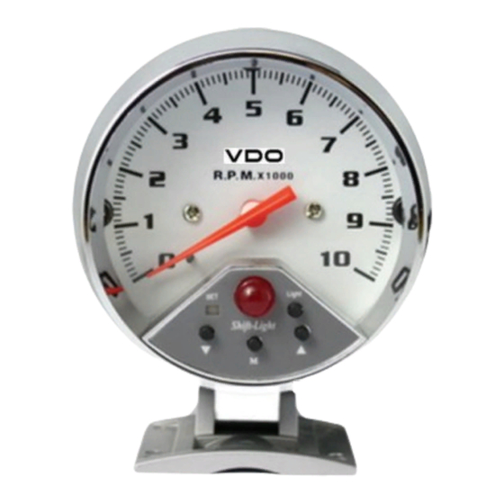
Installation p/n 333.001
Set the cylinder selector switch on the rear of the tachometer to the correct setting for your engine
(4, 6, or 8 cylinders).
Note: The red or black wire MUST be removed before adjustment to the cylinder setting, which is made from
the 田ylinder selector・switch.
Use a small screwdriver or similar object to reach into the recess. An ink pen works well.
Choose the best mounting position for your particular vehicle. Do not mount the tachometer in a
position that will impair visibility or interfere with driving. Before drilling into the mounting
surface. Look for any hidden wiring or other components that could be damaged by the drill
bit as it passes through. After mounting the tachometer, connect the wires as follows.
Disconnect negative (-) battery cable from your car battery.
Connect green wire from back of tachometer to vehicle's tachometer signal source.
CAUTION: You must consult your service manual to ensure the proper connection. If using an
aftermarket ignition system, be sure to follow the manufacturer's instructions.
Failure to do so can ruin your tachometer.
Connect black wire from back of gauge to a good engine ground. Do not assume that any part
of the chassis is a good ground. Use abrasive paper to clean any surface that will be serv-
ing as your ground connection.
Connect red wire to +12 Volt source that is energized only when the key is on the "on" position.
This can be at the fuse box or the ignition switch "on" position.
Connect yellow wire from back of gauge to 12 Volt terminal on ignition switch or other
switchable 12 Volt power source.
Reconnect negative (-) battery cable.
Final testing: Push the "Light" button to change the back light to 7 different color, Once a color
is selected, the tachometer will not change colors automatically. To resume this automatic
change of colors, press and hold the light button until it changes to the next color and then
release it.
Shift Light Operation
To see the RPM for the shift light:
Push the mode button "M" until the "set" green LED light is on, then push either the up or down
arrow button until the needle moves to the desired RPM.
Next, push the mode button "M" again, the "set" green LED light will go off and the tachometer will
return to the standard function.
FA 18 July 2011
Yellow Illumination + 12V
Red + 12V Ign.
Green Signal
Ignition
Coil
Black Negative
(Earth)
Distributor
Elect. Ign.
Module
Advertisement

Related Manuals for VDO 333.001


Summary of Contents for VDO 333.001
- Page 1 Module Black Negative (Earth) Installation p/n 333.001 Set the cylinder selector switch on the rear of the tachometer to the correct setting for your engine (4, 6, or 8 cylinders). Note: The red or black wire MUST be removed before adjustment to the cylinder setting, which is made from the 田ylinder selector・switch.
- Page 2 Yellow Battery + 12V Distributor Red + 12V Ign. Green Signal Ignition Coil Elect. Ign. Module Black Negative (Earth) Installation p/n 333.201 Set the cylinder selector switch on the rear of the tachometer to the correct setting for your engine (4, 6, or 8 cylinders). Note: The red or black wire MUST be removed before adjustment to the cylinder setting, which is made from the 田ylinder selector・switch.
- Page 3 Yellow Illumination + 12V Blue/White Temp Sender Orange Pressure sender Red + 12V Ign. Green Signal Ignition Coil Elect. Ign. Module Black Negative (Earth) Distributor Installation p/n 333.002 8 - 6 - 4 Cyl Setting at rear of Tacho Set the cylinder selector switch on the rear of the tachometer to the correct setting for your engine (4, 6, or 8 cylinders).