Table of Contents
Advertisement
Quick Links
Advertisement
Table of Contents

Related Manuals for ADB Safegate ACE2

Summary of Contents for ADB Safegate ACE2
- Page 1 Advanced Control Equipment (ACE2) User Manual 96A0357, Rev. G, 2019/11/08...
- Page 3 Where applicable, per FAA EB67 (applicable edition), ADB SAFEGATE L858(L) Airfield Guidance Signs are warranted against electrical defects in design or manufacture of the LED or LED specific circuitry for a period of 4 years. ADB SAFEGATE LED light fixtures (with the exception of obstruction lighting) are warranted against mechanical and physical defects in design or manufacture for a period of 12 months from date of installation;...
- Page 4 This manual could contain technical inaccuracies or typographical errors. ADB SAFEGATE BVBA reserves the right to revise this manual from time to time in the contents thereof without obligation of ADB SAFEGATE BVBA to notify any person of such revision or change. Details and values given in this manual are average values and have been compiled with care. They are not binding, however, and ADB SAFEGATE BVBA disclaims any liability for damages or detriments suffered as a result of reliance on the information given herein or the use of products, processes or equipment to which this manual refers.
-
Page 5: Table Of Contents
3.1 Advanced Control Equipment....................................5 3.2 Wall Mount............................................ 8 3.3 Internal-Mount..........................................8 3.4 Combo Box-Mount........................................9 3.5 Main Circuit Board........................................9 3.6 ACE2 Lamps-Out Monitoring Board..................................11 4.0 Modes of Operation................................13 4.1 Stand-Alone Configuration....................................13 4.2 Stand-Alone Push-button Description................................16 4.3 I/O Status display........................................17 4.3.1 Lamps-Out Calibration for Stand-Alone Mode.......................... - Page 6 Advanced Control Equipment (ACE2) TABLE OF CONTENTS Copyright ADB Safegate, All Rights Reserved ©...
-
Page 7: Safety
1.0 Safety Introduction to Safety This section contains general safety instructions for installing and using ADB SAFEGATE equipment. Some safety instructions may not apply to the equipment in this manual. Task- and equipment-specific warnings are included in other sections of this manual where appropriate. -
Page 8: Introduction To Safety
Advanced Control Equipment (ACE2) Safety 1.1.1 Introduction to Safety CAUTION Unsafe Equipment Use This equipment may contain electrostatic devices, hazardous voltages and sharp edges on components • Read installation instructions in their entirety before starting installation. • Become familiar with the general safety instructions in this section of the manual before installing, operating, maintaining or repairing this equipment. -
Page 9: Advanced Control Equipment
Carry out troubleshooting on the Advanced Control Equipment. 2.2 How to work with the manual 1. Become familiar with the structure and content. 2. Carry out the actions completely and in the given sequence. 96A0357, Rev. G, 2019/11/08 Copyright ADB Safegate, All Rights Reserved ©... - Page 10 Advanced Control Equipment (ACE2) Advanced Control Equipment Copyright ADB Safegate, All Rights Reserved ©...
-
Page 11: Introduction
(CCR) monitor, performing all L-827/L-829 functions in accordance with FAA AC 150 /5345-10. The ACE2 is a universal device that can be used to control any type of CCR and/or controlled element regardless of the manufacturer. - Page 12 The result of this is real-time communication between all of the ACE2 and ACE units and the rest of the ADB SAFEGATE L-890 ALCMS, even if a network connection fails in one of the ACE2 or ACE units.
-
Page 13: Specifications
Graphics User Interface (GUI) The ACE2 graphic user interface (GUI) consists of the 128 x 64 pixel monochrome LCD display and four momentary switch buttons. In typical modes of operation, the upper half of the LCD displays a monitored parameter or in the stand-alone mode a configuration menu. -
Page 14: Wall Mount
Refer to Figure 2. The ACE2 is a universal device that is used to control most types of CCRs and/or controlled elements regardless of the manufacturer. The ACE2 printed circuit boards are mounted inside a small and rugged environmental enclosure that can be:wall-mounted, placed on a CCR, or enclosed in the CCR itself. The ACE2 consists of microprocessor- based module(s) that process communication, control commands, input/ output interface, and failsafe functionality for controlled elements in the airfield lighting vault. -
Page 15: Combo Box-Mount
A communication circuit provides the interface for the redundant communication network (RCN), which is how ACE2 receives and transmits data to the ALCMS vault computer. It contains a fiber optic interface connection for the Current Voltage Monitor (CVM), optional Insulation Resistance Monitoring System (IRMS), and an RS-232 local configuration interface. - Page 16 On/Off power switch to ACE2 RY7 general fault relay Relay Fuse ACE2 Power Supply Circuit The ACE2 Power Supply circuitry is integrated into the Main Circuit Board (shown in Figure 5). It provides the internal system with a regulated and isolated power source.
-
Page 17: Ace2 Lamps-Out Monitoring Board
If the ACE2 contains only one Lamps- Out board, the settings are: • Switch 1 - Off • Switch 2 - Off If the ACE2 contains a second Lamps-Out board, the SW1 settings on the second board are: • Switch 1 - Off • Switch 2 - On If the ACE2 contains a third Lamps-Out board, the SW1 settings on the third board are •... - Page 18 Advanced Control Equipment (ACE2) Introduction Copyright ADB Safegate, All Rights Reserved ©...
-
Page 19: Modes Of Operation
3. L-890 ALCMS. 4.1 Stand-Alone Configuration The ACE2 is only set up for stand-alone operation by qualified ADB Safegate personnel. In this mode, configuration of the ACE2 is performed through the local menu and alternative functions of the buttons listed in Figure 1. - Page 20 Advanced Control Equipment (ACE2) Modes of Operation Table 2: ACE2 Stand-Alone Configuration Short Reference (continued) Button Action 2 ↓ , 3 ←, 1 2 ↓ , 3 modify Menu Item Parameter Possible value Description Select the Meg Voltage based on the regulator. The smaller regulators voltage...
- Page 21 Figure 7: ACE2 Stand-Alone Configuration Flowchart Most of the parameters are self explanatory. The “Meg Now” command initiates an immediate insulation resistance measurement regardless of the schedule. The “Meg Timer Reset” restarts the megging schedule. The next megging shall occur at the end of the “Meg Period” and periodically after that.
-
Page 22: Stand-Alone Push-Button Description
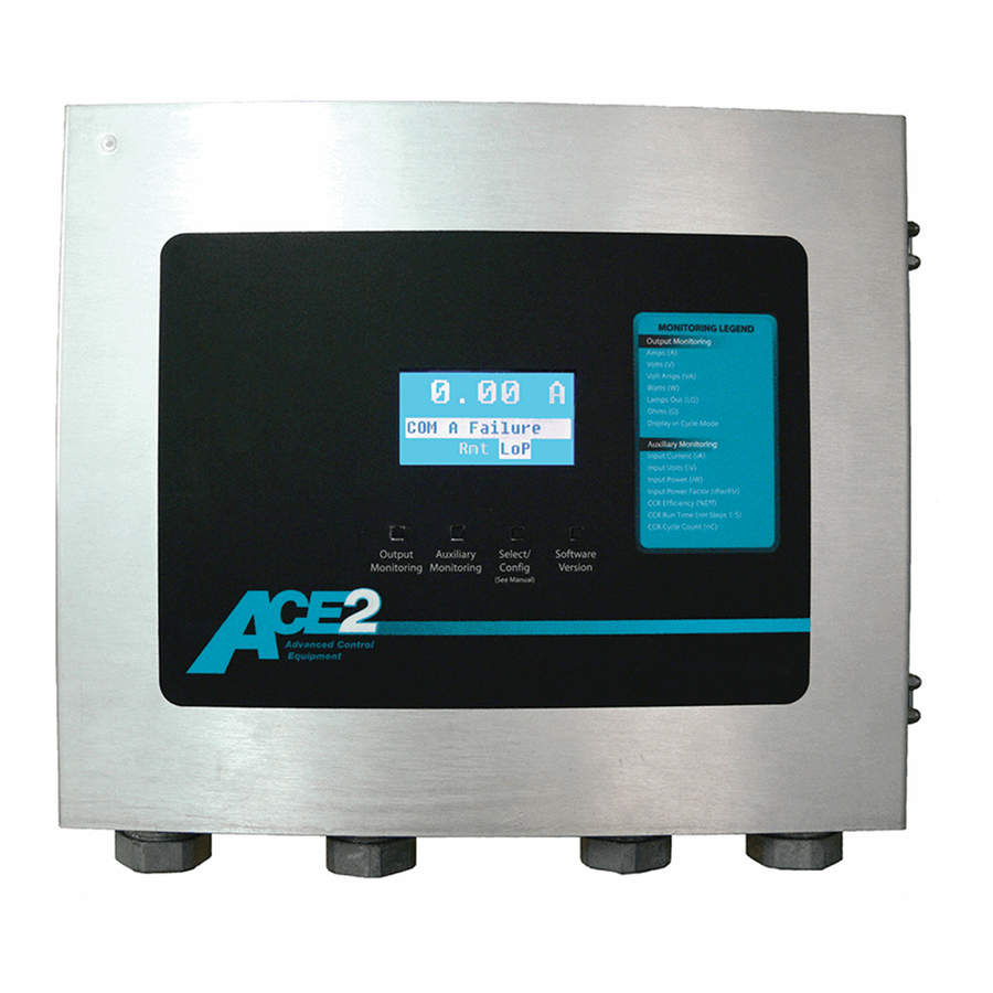
Monitoring Legend and the Pushbutton Functions. Figure 8: ACE2 Legend and Button Enlargement Note The buttons and the monitoring legend are the same for all ACE2 units. Refer to Figure 9. The push-buttons are described left to right as 1 through 4, and their functions are as follows:... -
Page 23: I/O Status Display
Note Out ?????? means there is nothing written to the outputs since power-up and the latching relay status is unknown. 96A0357, Rev. G, 2019/11/08 Copyright ADB Safegate, All Rights Reserved ©... -
Page 24: Lamps-Out Calibration For Stand-Alone Mode
4.3.1 Lamps-Out Calibration for Stand-Alone Mode In order for the ACE2 to correctly calculate the number of lamps burned-out it has to be calibrated. For best accuracy, the lamps-out calibration is done only when CCRs are loaded to 75% or more of their specified rating. For best accuracy, all lamps on the lamp circuit being calibrated have the same wattage rating, otherwise the lamps-out detection is not as accurate on lamp wattages not used in the calibration process. -
Page 25: Installation
The installation conforms to the applicable sections of the National Electric Code and local codes. The ACE2 is mounted either as a Remote-mount, a Wall-mount, a Combo Box-mount, or an Internal-mount. The following subsections describe each of these mounting options. -
Page 26: Ace2 Cabling Entry
Installation Figure 10: Wall-Mount, Interior View Locate each ACE2 unit as close as possible to the controllable elements, the Regulator, the Generator etc. Mount the CVM and the IRM board (if present) separately from the ACE2. Mount the Wall-mount ACE2 flush against a wall or on U-channels that support all four corners of the enclosure. - Page 27 ONLY as seen in Figure 14.Protect ALL electronic equipment in the ACE2 enclosure while installing conduit. Figure 11: Wall-Mount, Bottom View Figure 12: Wall-Mount, Top View 96A0357, Rev.
- Page 28 Advanced Control Equipment (ACE2) Installation Figure 13: Wall-Mount, Conduit Drawing Note DO NOT blow out enclosures because metal shavings can damage the electronics. Copyright ADB Safegate, All Rights Reserved ©...
-
Page 29: Internal-Mount Installation
CCR. Only running and connecting external ACE2 communications wiring among other ACE, ACE2, and the Vault computer is required. The ACE2 is located on the interior, attached to the hinged door. To gain access to the ACE2, open the CCR door, unlatch and open the ACE2 enclosure door. - Page 30 5. Attach all conduits to the bottom or to the top access plate ONLY as seen in Figure 6. Protect ALL electronic equipment in the ACE2 enclosure while installing conduit to the BOTTOM or to the TOP access plate. Copyright ADB Safegate, All Rights Reserved ©...
-
Page 31: Ace2 Cable Entry
5.4.1 ACE2 Cable Entry Note All conduit and wiring must only enter the ACE2 enclosure through the bottom or through the top access plate. This facilitates quick maintenance and replacement of the ACE2 unit. DO NOT blow out enclosures because metal shavings can damage the electronics. - Page 32 Advanced Control Equipment (ACE2) Installation Figure 20: Combo Box-Mount, Top Detail Figure 21: Combo Box-Mount, Conduit Drawing Copyright ADB Safegate, All Rights Reserved ©...
-
Page 33: Troubleshooting
6.0 Troubleshooting This section contains troubleshooting information. The information covers only the most common problems. If a solution to the problem is not found with the information given here, contact the local ADB Safegate representative for help. 6.1 Troubleshooting Procedures Troubleshooting procedures for the Advanced Control Equipment (ACE2) are in this section. - Page 34 No power. Verify the IRMS has power. 10. Periodic IRMS megging is not Fiber optic cable not connected. Check the fiber optic connection from the IRMS to the ACE2 being performed IRMS configuration not set processor board. properly. Verify the IRMS date, time, and period are set correctly.
-
Page 35: Error Messages
Power up the other unit. COM A Failure connected though COM A is not Check to ensure the cable is securely attached to the ACE2, as powered up. well as the other unit to communicate with. The COM A cable is unplugged or loose. -
Page 36: Wiring Schematics
In Local Control mode. 6.3 Wiring Schematics This section provides wiring schematics for L-827/L-829 Advanced Control Equipment (ACE2). See Figure 30 for the L-827/L-829 ACE2 wiring connections to the constant current regulator (CCR). Copyright ADB Safegate, All Rights Reserved ©... -
Page 37: Connectors
Discreet Output Com A RS-422 Com B RS-422 LCD Board Ribbon Cable Connector LCD Connection Ribbon Cable Connector External Keypad Connection ACE2 External Display Power Configuration Port RS-232 Non-Volatile Memory CVM Fiber Optic Port Internal Power Present LED D7 thru D15... - Page 38 Advanced Control Equipment (ACE2) Troubleshooting Figure 23: ACE2 PCB to URCII/I PCB for CCF 3 and 5 Step CCR Figure 24: ACE2 PCB to CCT 3 and 5 Step Control PCB Copyright ADB Safegate, All Rights Reserved ©...
- Page 39 Figure 25: ACE2 Internal and Combo Box Wiring 96A0357, Rev. G, 2019/11/08 Copyright ADB Safegate, All Rights Reserved ©...
- Page 40 Advanced Control Equipment (ACE2) Troubleshooting Figure 26: ACE Combo/Wall-Mount Internal Copyright ADB Safegate, All Rights Reserved ©...
-
Page 41: Parts
7.0 Parts To order parts, call ADB Safegate Customer Service or the local ADB Safegate representative. Use this four-column parts list to describe and locate parts. This description uses a fictional number to show the use of the parts list sections. It does not provide the actual parts list. - Page 42 Advanced Control Equipment (ACE2) Parts Copyright ADB Safegate, All Rights Reserved ©...
-
Page 43: Support
Table 11: ADB SAFEGATE Support Live Technical Support - Americas If at any time you have a question or concern about your product, just contact ADB SAFEGATE’s technical service department. Trained in all areas of system issues, troubleshooting, quality control and technical assistance, our highly experienced Technical support specialists are available 24 hours a day, seven days a week to provide assistance over the phone. -
Page 44: Recycling
A.2.1 Local authority recycling The disposal of ADB SAFEGATE products is to be made at an applicable collection point for the recycling of electrical and electronic equipment. The correct disposal of equipment prevents any potential negative consequences for the environment and human health, which could otherwise be caused by inappropriate waste handling. - Page 45 Tel.: +46 (0)40 699 17 00, Internet: www.adbsafegate.com Fax: +46 (0)40 699 17 30 ADB SAFEGATE Airfield Technologies Ltd. China ADB SAFEGATE, China: Unit 603, D Block, CAMIC International Convention Center, No 3, Hua Jia Di East road, ChaoYang district, Beijing 100102 P.R.
Need help?
Do you have a question about the ACE2 and is the answer not in the manual?
Questions and answers