
Related Manuals for ABB Tmax T8 L5757


Summary of Contents for ABB Tmax T8 L5757
- Page 1 Instructions for installation Instructions for installation, service and and service maintenance of low voltage moulded case circuit-breakers Tmax T8 1SDH000682R0002 L5757...
- Page 2 Drwg. Resp.Off. LB-DTAT Title Language Instructions for installation, service and maintenance of low voltage moulded User Offi ce App. case circuit-breakers Mod. Scale L3692 L5757 Apparatus Tmax T8 L3885 Doc N° 1SDH000682R0002 ABB SACE Division...
-
Page 3: Table Of Contents
Index Measures to be taken if operating faults occur ..20 Description ..............5 Accessories .............. 21 General characteristics ............5 10.1 Electrical accessories ............21 External front view of the circuit-breaker ......5 10.2 Mechanical locks ..............23 1.3.1 IEC circuit-breaker rating plate data ........ - Page 4 Mod. L3692 L5757 Scale Apparatus Tmax T8 L3885 Doc N° Page N° 1SDH000682R0002 4/39...
-
Page 5: Description
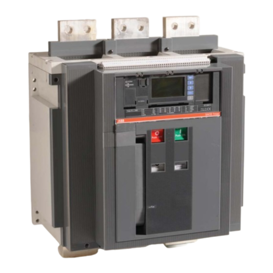
Description General characteristics Tmax T8 circuit-breakers and disconnectors consist of a plastic structure which houses the operating mechanism, the poles and the auxiliary parts. Each pole is insulated from the others and contains the circuit breaking parts and the current sensor of the corresponding phase. The fi... -
Page 6: Installation
Comply with the following instructions when lifting the circuit-breaker: the circuit-breakers must be placed on a sturdy surface and preferably lifted with an appropriate fork-lift truck. The use of ropes is, however, permitted: In this case, the lifting ropes ust be attached as shown in the fi gure. Fig. -
Page 7: Electrical Connections
Electrical connections Power circuit connections Use insulated bars/ perform specifi c type tests on the installation. 5.1.1 Shapes of the terminals VR/HR Adjustable rear termi- Front terminals Extended front Vertical rear ter- Vertical rear nals for fl at bar ( VR for (IEC/UL) terminals (IEC) minals (IEC) -
Page 8: Assembly Procedures For The Connection Busbars
Positioning the fi rst anchor plate of the busbars Anchoring to the switchboard 7.48" 7.48" 7.48" 7.48" 7.48" 7.48" 7.48" Fig. 11 5.2.3 Assembly procedures for the connection busbars Check the state of the contact surfaces of the connections very carefully: they must be very clean and free from burrs, dents and traces of rust - which must be removed with a fi... -
Page 9: Putting Into Service
Putting into service General procedures – Make sure that the power connections to the circuit-breaker terminals are tight – Perform al the preparatory operations on the release – Make sure that the power supply voltage of the auxiliary circuits is between 85% and 110% of the rated voltage of the electrical applications –... -
Page 10: Instructions For Use
Instructions for use Operating and signalling components 1 Push-button for the manual opening operation 2 Lever for manual loading of the closing springs 3 Mechanical indicator for circuit-breaker open “O” and closed “I” 4 Mechanical indicator for protection release tripped 5 Pushbutton for the manual closing operation 6 Indicator for springs loaded - unloaded 7 Operation counter (to order) - Page 11 c) Circuit-breaker closing This operation can only be carried out when the closing springs are fully loaded. Press the push-button (5) marked with the letter “I” for closing in the manual mode. When there is a shunt closing release, the operation can also be carried out in the remote mode by means of the special control circuit.
-
Page 12: Maintenance
WARNING RISK OF ELECTRIC SHOCK: Risk of electric shock or accident. ABB declines all liability for damage to persons or property caused by failure to comply with the instructions in this document. The maintenance operations must be performed by skilled personnel with detailed knowledge of the equipment. -
Page 13: First Level Maintenance Operations
8.3. First Level maintenance operations 8.3.1. Preliminary operations: - open the circuit-breaker and make sure that the springs of the operating mechanism are unloaded. WARNING: if work must be performed on the circuit-breakers, disconnect the power circuit and auxiliary circuits and earth the terminals in a visible way on both the supply side and load side. -
Page 14: Mechanical Operating Mechanism
- If the undervoltage release is installed, disassemble the coil support and unload the springs of the operating mechanism by closing and opening the circuit-breaker. Fig. 20 8.3.5. Mechanical operating mechanism - Clean the points indicated in fi gure 21. Use a cleaning product such as Henkel’s 273471 or equivalent if there is a heavy coat- ing of dirt. -
Page 15: Protection Releases
8.3.7. Protection releases - -Power the protection release with a PR030/B battery unit. - Make sure that the protection release functions correctly: release test with the “Trip Test” (PR232, PR331, PR332) and “Autotest” (PR332) - With release PR332, make sure that the front leds or display do not indicate the presence of alarms. - With release PR232 and PR331, make sure that the front leds do not indicate the presence of alarms. -
Page 16: Second Level Maintenance Operations
8.4. Second Level maintenance operations 8.4.1. Preliminary operations: - open the circuit-breaker and make sure that the springs of the operating mechanism are discharged. WARNING: if work must be performed on the circuit-breakers, disconnect the power circuit and auxiliary circuits and earth the terminals in a visible way on both the supply side and load side. -
Page 17: Mechanical Operating Mechanism
Fig. 27 - Contact ABB Sace (*) if the springs are deformed or tarnished, if rings are missing or if the control is excessively worn. (*) ABB may replace spare parts type “A” after having obtained the customer’s approval. -
Page 18: Electrical And Mechanical Accessories
8.4.6. Electrical and mechanical accessories - Make sure that the accessories are securely fi xed to the circuit-breaker. - Make sure that the electrical accessories are correctly connected to the circuit-breaker. - Gearmotor: after every 10000 operations, check the brushes for wear and replace the gearmotor if necessary. - Make sure that the releases (YO, YU, YC) are in good conditions (absence of excessive wear, overheating, breakages) Fig. -
Page 19: Maintenance Operations; Fi Nal Inspections
8.4.9. Maintenance operations; fi nal inspections - Fit all the parts back in place and re-connect the auxiliary power supply if necessary. - Re-assemble the escutcheon plate as shown in fi gure 30. 1,1 Nm Fig. 29 - Using the different auxiliaries in succession, perform the operations 10 times: - Opening (in both the local and remote modes, if applicable) - Closing (in both the local and remote modes, if applicable) - Release by means of the trip test via relay... -
Page 20: Measures To Be Taken If Operating Faults Occur
• power supply circuit tional diagram • • Coil damaged Replace the coil Operate in the manual mode. Contact ABB SACE • • Operating mechanism locked if the fault persists • • Open position key lock activated Unlock by inserting the key Check the relative supply circuit and the supply •... -
Page 21: Accessories
10. Accessories 10.1 Electrical accessories Shunt opening / closing release (YO/YC) and second shunt opening release (Y02) Allows the device to be opened or closed by remote control. Given the characteristics of the circuit-breaker operating mechanism, opening (with the circuit-breaker closed) is always possible, whereas closing is only possible when the closing springs are loaded. Most of the releases can operate with both direct and alternate current. - Page 22 Time-delay for undervoltage release (UVD) The undervoltage release can be used in conjunction with an electronic time-delay device, which must be installed outside the circuit-breaker and which delays release tripping with preset, adjustable times. Use of the delayed undervoltage release is useful for preventing trips when the power supply network of the release may be subject to power cuts or brief voltage dips.
-
Page 23: Mechanical Locks
– Operating mechanism – PR030/B Ultra power supply unit – Dust-guard fl ange for compartment door – Lubricating grease for the operating mechanism – Tool case Ask for the ABB spare parts catalogue for further details. Mod. L3692 L5757 Scale... -
Page 24: Protection Releases - References
PR332/PR333 Getting started 1SDH000650R0501 ABB SACE PR232/P-T8 microprocessor-based electronic release 1SDH000650R0502 ABB SACE PR331 T8 microprocessor-based electronic release 1SDH000650R0503 ABB SACE PR332 T8 microprocessor-based electronic release 11.1 Safety notes WARNING: this symbol highlights information about operations, actions or circumstances that can cause injuries to the personnel, damage to the unit or economic losses. -
Page 25: Overall Dimensions
12. Overall dimensions Version with front terminals 1600A/2000A/2500A - F (IEC/UL) 1 Inside edge of compartment door 2 Drilled M8 holes for fi xing circuit- breaker (use M8 screws) Insulating or insulated metal wall Fig. 31 Mod. L3692 L5757 Scale Apparatus L3885 Doc N°... - Page 26 Version with extended front terminals 2000A/2500 - ES (IEC) 1 Inside edge of compartment door 2 Drilled M8 holes for fi xing circuit- breaker (use M8 screws) Insulating or insulated metal wall Fig. 32 Mod. L3692 L5757 Scale Apparatus L3885 Doc N°...
- Page 27 Version with adjustable rear terminals in fl at bar 2000A/2500A* - HR (IEC) / VR (IEC-UL) *NOTE: if installed vertically, the adjustable rear terminals in fl at bar are also suitable for 3200A (IEC). 1 Inside edge of compartment door 2 Drilled M8 holes for fi...
- Page 28 Version with vertical rear terminals 3200A - VR (IEC) 1 Inside edge of compartment door 2 Drilled M8 holes for fi xing circuit- breaker (use M8 screws) Insulating or insulated metal wall Fig. 34 Mod. L3692 L5757 Scale Apparatus L3885 Doc N°...
- Page 29 Version with vertical rear terminals 3000A - VR (UL) 1 Inside edge of compartment door 2 Drilled M8 holes for fi xing circuit- breaker (use M8 screws) Insulating or insulated metal wall Fig. 35 Mod. L3692 L5757 Scale Apparatus L3885 Doc N°...
- Page 30 Compartment dimensions Holes drilled in compartment door Depth 3 POLES 4 POLES Fig.36 Fig.37 Insulation distances for installation in metal cubicle Fig.38 Mod. L3692 L5757 Scale Apparatus L3885 Doc N° Page N° 1SDH000682R0002 30/39...
-
Page 31: Circuit Diagrams
13. Circuit diagrams WARNING: Carefully read notes F and O on the circuit diagrams before installing the circuit-breaker. OPERATING STATE SHOWN The diagram illustrates the components in the following conditions: - circuit-breaker open - circuits de-energized - releases not tripped - motor operator with unloaded springs. - Page 32 43 - 44 - 46 NOTES A) The circuit-breaker is only fi tted with the accessories specifi ed in the ABB SACE order acknowledgement. Consult this catalogue for instructions about how to make the order. B) The undervoltage release is supplied for operation using a power supply branched on the supply side of the circuit-breaker or from an independent source: the circuit-breaker can only close when the release is energized (there is a mechanical lock on closing).
- Page 33 X) Poles T3 and T4 of connector XV are reserved for voltage measurements if U>690 V. In this case, they must be connected to the secondary of the voltage transformer TU (see fi g. 44). Ask ABB SACE for residual current applications with over 690 V voltage values.
- Page 34 Circuit diagram - Operating state Four-pole circuit-breaker with PR232/P-T8, PR331/P or Three-pole circuit-breaker with PR232/P-T8, PR331/P or PR332/P electronic release PR332/P electronic release Three-pole or four-pole switch- Three-pole circuit-breaker with PR332/P electronic release, disconnector residual current protection and U<=690 V. Mod.
- Page 35 Motor operator, opening, closing and undervoltage releases Signalling contacts Mod. L3692 L5757 Scale Apparatus Tmax T8 L3885 Doc N° Page N° 1SDH000682R0002 35/39...
- Page 36 Auxiliary circuits of releases PR331 and PR332 ATTENZIONE: vedere nota F WARNING: read note F ATTENZIONE: vedere nota F ACHTUNG: Anmerkung F WARNING: read note F ATTENTION: lire remarque F ACHTUNG: Anmerkung F ATENCIÓN: leer la nota F ATTENTION: lire remarque F ATENCIÓN: leer la nota F Uaux.
- Page 37 Auxiliary circuits of the PR332 release with communication module PR330/D-M connected to actuator unit PR330/R PR120/K signalling module Mod. L3692 L5757 Scale Apparatus Tmax T8 L3885 Doc N° Page N° 1SDH000682R0002 37/39...
- Page 39 Since both the Standards and materials used are subject to continual developments, the characteristics and over- all dimensions given in this catalogue may only be con- sidered binding after they have been confi rmed by ABB. ABB S.p.A. ABB SACE Division Via Baioni, 35 - 24123 Bergamo - Italy Tel.: +39 035.395.111 - Telefax: +39 035.395.306-433...
Need help?
Do you have a question about the Tmax T8 L5757 and is the answer not in the manual?
Questions and answers