Advertisement
Quick Links
Advertisement

Related Manuals for Unical BCM 2.0

Summary of Contents for Unical BCM 2.0
- Page 1 BCM 2.0 BOILER CONTROL MANAGER INSTALLATION AND MAINTENANCE INSTRUCTIONS...
- Page 2 General Information BCM is able to operate: as a HCM (Heating Cascade Manager). This as a signal boiler controller. This enables con- enables control of the complex structure of sev- trol of basic services of the heating system and eral heat generators. includes system safety devices Description Description...
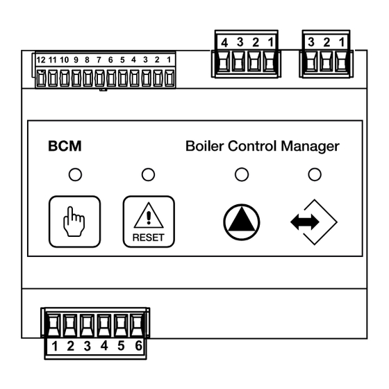
- Page 3 LOCAL CONNECTORS HOST CONNECTORS to manage the boiler/cascade to manage the system remotely S.E. Description S.E. Description A1 Internal boiler connections A (PLC) Modbus 14 SMG Global flow sensor B (PLC) eBUS + Est. Cascade Regulator 13 SRG Global return sensor 12 DK Water deficiency safety eBUS -...
-
Page 4: Key To Wiring Di- Agram
COM. Common output P.Car. Storage tank loading pump P. CH Heating pump 12 11 10 9 8 7 6 5 4 3 2 1 P. Car. Stemp ACC. P.Coll. Manifold pump 12 11 10 9 8 7 6 5 4 3 2 1 ALARM Alarm output S.E. - Page 5 Application CASCADE MANAGER REMOTE CONTROL • eBUS communication interface with SHC BMM • eBUS communication interface for HCM at a modules higher level • Cascade management with maximum 8 boilers • Modbus communication interface to integrate • Global return temperature detection into an automation system in the building.
- Page 6 to edit BCM parameters (see chap. 2.8 - USER INTERFACE devices menu) 3.1 - BCM (HCM) parameters - General settings / user settings Code Sym- Value Description Default BCM user settings settings Enabled services All services disabled Heating only Antifreeze only Heating + Antifreeze DHW only Heating + DHW...
- Page 7 Code Sym- Value Description Default BCM user settings settings °C DHW: Minimum Set-point 250 ÷ 450 °C DHW: Maximum Set-point 500 ÷ 650 Heater Adjustment 0 ÷ 15 0 = 85° - 1 ÷ 15 = °K DHW: Temp. Requested Differential -20 ÷...
- Page 8 Code Sym- Value Description Default BCM user settings settings Unit temperature °C / °F 0 ÷ 1 Application Code Burners cascade (BMM) Individual burners (only 1 BMM connected) Programmable Relay #1 Main pump control Boiler status Programmable Relay #2 activated only if the fault prevents inputting the requested number burner correctly.
- Page 9 3.2 - BCM (HCM) parameters - CH and DHW general settings / user settings To enable the request, close the contact between pin 12 and pin 9 with a jumper. Also jump pin 12 and 11 (INAIL input alarm) or use it to manage the system's safety devices.
- Page 10 3.3 BCM (HCM) parameters - 0 - 10 V user settings. With this configuration the system will set a temper- ature based on the voltage received from the 0 - 10 V input. The setting will be between the value of the param- eter 31 (minimum) and 39 (maximum).
- Page 11 3.4 BCM (HCM) - Settings for use with Modbus As well as with 0-10V, the boiler can also be controlled with Modbus Modbus Notes: 12 11 10 9 8 7 6 5 4 3 2 1 The tables with the Modbus records is available on the website with the tech- nical info To change the modbus address (default...
- Page 12 3.5 - Error code When the boiler detects a fault, the alarm symbol is displayed on the user interface display. You can reset the boiler by pressing: - key R from the user interface or key RESET from BCM. DESCRIPTION SOLUTIONS CODE detected on BCM (HSC)
- Page 13 FloW-ReTuRn ∆T MaxiMuM RESET: AUTO PRESSURE Check circulation, check Effect: Stop burner, Pump on at installation maximum speed. FLOW Circulation control OVERTEMPERATURE. It is activated when the flow temperature is > 95. Resetting is automatically carried out when the temperature is < 80. Effect: Stop burner, Pump on at maximum speed.
- Page 14 CLOGGED OUTLETS RESET: MANUAL It is detected from the CO sensor Check the Chimneys / Check the trap. if the COC = 1 or 2 parameter is ena- bled. If COC = 2, the COL sensor is con- trolled to detect chimney obstruc- tion with low air intake conditions.
- Page 16 - export@unical-ag.com - www.unical.eu Unical shall not be held liable for any inaccuracies due to transcription or printing errors. Furthermore, it reserves the right to modify its products as deemed necessary or useful, without aff ecting their essential features.
Need help?
Do you have a question about the BCM 2.0 and is the answer not in the manual?
Questions and answers