Table of Contents
Advertisement
Advertisement
Table of Contents

Related Manuals for MAKINEX PHT2-140

Summary of Contents for MAKINEX PHT2-140
- Page 1 Rev 0919...
-
Page 2: Table Of Contents
CONTENTS FORWARD ........................ 3 DISCLAIMER ......................3 1. INTRODUCTION ....................4 2. SAFETY INFORMATION ..................5 2.1 Training ......................5 2.2 Preparation ....................... 5 2.3 Operation ......................5 2.4 Maintenance and Charging ................6 2.4.1 Adjusting brakes ..................6 2.4.2 Securing nose hook onto jib .............. -
Page 3: Forward
Thank you for purchasing a MAKINEX product. This manual provides information and procedures to safely operate and maintain the PHT2-140 device. For yours and/or other’s safety and protection from injury, carefully read, understand and observe the safety instructions described in this manual. -
Page 4: Introduction
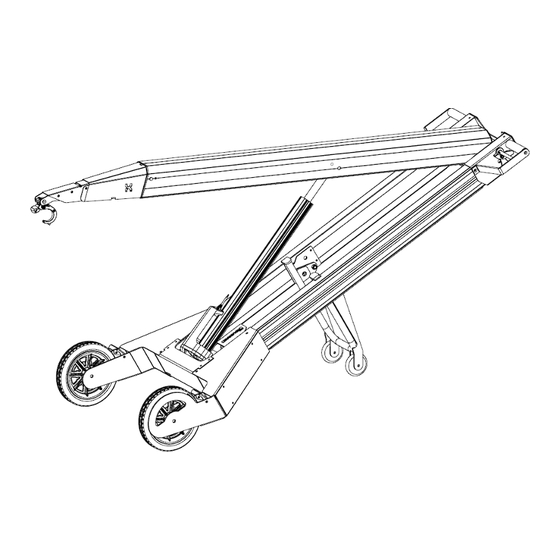
1. INTRODUCTION The PHT2-140 device is a hand truck with a powered lifting arm which can be fitted with various attachment tools. The basic PHT2-140 device is configured in combination with a hook attachment fitted to the lifting arm. Typically, the device is used for loading small machinery fitted with a lifting eye onto or off vehicles –... -
Page 5: Safety Information
Do not exceed the rated lifting capacity – 140kg (120kg for all other attachments). • Understand the LOAD DATA page and operate within comfortably manageable limits – the PHT2-140 device’s capacity should never be more than comfortably manageable by user and always less than or equal to 140kg (120kg for all other attachments). -
Page 6: Maintenance And Charging
2.4.1 Adjusting brakes Over time the brakes of your PHT2-140 may need to be adjusted to keep your machine running at its optimum capacity, the following instructions will allow you to do so yourself in simple, easy to follow, steps. - Page 7 To tighten or loosen PHT2-140 brakes: 1. Lie your powered hand truck down on a bench or flat surface with folding support wheels folded to take load off the large wheels. 2. Ensure brakes are disengaged. 3. Remove side plate on right hand side of unit using Phillips head screw driver.
- Page 8 The pad should not be touching the rubber. 7. Re-tighten retainer nut after desired adjustment is achieved. 8. Place PHT2-140 back on the ground and test brakes. If working correctly replace the side plate that was removed (in step 3) and use resume normal use.
-
Page 9: Securing Nose Hook Onto Jib
2.4.2 Securing nose hook onto jib Insert the tabs of the nose hook assembly into the jibs mounting slots and secure using an M10x135mm Button Head Cap Screw & M10 Nyloc Nut. Page 9 of 37... - Page 10 Pack the device for transport so that on/off switch can’t be accidently turned ON during transport • Store out of weather, do not leave the machine in the rain or wet conditions. • Lift PHT2-140 using carry points on wheel guards and handles Lifting point Page 10 of 37...
-
Page 11: Operation
3. OPERATION 3.1 Controls/Layout Removable Nose Cone Safety Locking Hook Powered Lifting Arm Linear Actuator Handle Brake Adjust compartment Brake Removable Battery Locking Plunger Folding Support Lift arm control Wheels Brake release lever On/Off Switch Page 11 of 37... -
Page 12: General
• Being able to ‘reach out’ with the hook is fundamental to the operation and function of the PHT2-140 device. • Hook Reach can be varied by raising or lowering the handle. •... -
Page 13: Steering While Unloaded
• This function of laterally pivoting the machine on the rear wheels is particularly useful when lining up the PHT2-140 device for a lift. • The device can be crabbed sideways in order to position the lifting hook in line with lifting eye. -
Page 14: Loading And Unloading At Ground Level
3.2.5 Loading and unloading at ground level This section explains how to get a load at ground level engaged onto the device and in a hands neutral position. A hands neutral position is when the device is loaded, and the load is balanced against the weight of the device resulting in minimal balancing force required by the hands. -
Page 15: Hook Operation
3.2.6a Hook Operation • Hook operation is designed to enable one-man hook engagement and disengagement in a fixed lifting point. • For flexible lift point such as a sling, the hooks self-locking mechanism engages as load is applied. Hence aiding single man operation. •... -
Page 16: Hook Operation
3.2.6b Hook Operation NO LOAD LOADED The hooks unique mechanism allows it to naturally self-lock as it is loaded and spring open when unloaded. Page 16 of 37... -
Page 17: Operating Brakes
3.2.7 Operating Brakes • Brakes work like the park brakes on a car • Once engaged, it will automatically stay on until released • Brake Engaged Brake Disengaged Brake Catch Release Brake Handle Engaging Brake • Releasing Brake Brakes can be easily applied by pulling the brake handle towards the handle bar Activating Brake... -
Page 18: Ground Conditions
3.2.8 Ground Conditions • Firm ground is required for loading and unloading with the PHT2-140 device. Concrete, asphalt, rolled road base are suitable. • Small stones or bumps can reduce the ability to manoeuvre the loaded device into a good position for executing a lift. -
Page 19: Lift Technique
3.3 Lift Technique 3.3.1 Raising & lowering load • These figures show different load heights in the hands neutral position • Keep device stationary while raising load. • Once load height clear of platform, carefully move wheels closer. • Apply brakes and begin the unload procedure. •... -
Page 20: Loading & Unloading At Height
3.3.2 Loading & Unloading at height • Be certain the platform can take the weight of the load. • Only attempt to transfer the load to an elevated platform that can take the weight. • Have a firm footing – device can pull user towards load in high load, high reach situations. •... - Page 21 • Once load is above platform and safely beyond edge – lower the lifting arm to lower the load onto platform and take weight off hook • Disengage brake and remove hook • See section 3.2.6 for Hook Operation detail Figure shows backing device away from unload procedure whilst lowering the lifting arm REVERSE SEQUENCE –...
-
Page 22: Increased Risk Position
3.3.3 Increased Risk Position Figure shows hands raised above Chest Height If wheels were closer to the platform the operator would require less Reach • The above position shows extended reach and hands raised above chest height. • It is in this region that heavy load can become unmanageable because of the force required to control the handles. -
Page 23: Charging
3.4 Charging • The 18V Lithium Ion battery can be recharged with an external charger. • Top up battery regularly. • Full charge from the low battery level will take 1.5 hours. • A full battery will sustain around 45 load and unload cycles at 90kg. •... -
Page 24: Transport And Storage
If linear actuator or power fails preventing the ability to lower the Powered Lifting Arm, follow these instructions: • If lifting arm is low enough, place load on the ground and disengage it, if lifting arm is close to a bench or platform, place load on the platform and disengage it. •... - Page 25 Slide machine on or off utility vehicle Up to 25kg lift • When using device on a day to day basis – time and battery power is saved by leaving the device as illustrated between uses. Page 25 of 37...
-
Page 26: Load And Reach Data
Loaded Hands Neutral Position, Transporting or Lifting, no brakes applied • This is called the ‘Hands Neutral Position’ where the weight of the load balances against the weight of the PHT2-140 machine leading to little (neutral) weight in the users hands. •... -
Page 27: Slope Guide
5. SLOPE GUIDE Page 27 of 37... -
Page 28: Quick Reference Hazard Assessment
6. QUICK REFERENCE HAZARD ASSESSMENT Page 28 of 37... - Page 29 Page 29 of 37...
-
Page 30: Safety And Instruction Decal
7. SAFETY AND INSTRUCTION DECAL Page 30 of 37... -
Page 31: Technical Data And Specifications
8. TECHNICAL DATA AND SPECIFICATIONS 2075 2175 MACHINE SPECIFICATIONS Lift Capacity Up to 140kg / 308lbs (120kg / 264lbs for all other attachments) Linear Actuator 12V 25Amp Hook Height Range Ground to 1.9m Total 40kg ▪ Handle end - 15kg Weight of Machine ▪... -
Page 32: Charger Specifications
9. CHARGER SPECIFICATIONS Page 32 of 37... -
Page 33: Limited Warranty
MAKINEX product in peak operating condition. MAKINEX warrants each new Powered hand truck to be free from defects in material and workmanship under normal domestic and industrial use and service for the period specified below, conditional to the limitations and exclusions printed on this page. -
Page 34: Warranty Exclusions
Failures due to acts of God and other force majeure events beyond the manufacturer’s control. Problems caused by parts that are not original MAKINEX parts. Responsibility of the consumer under this Limited Warranty: Proper maintenance and safety checks need to be performed before operation of the machine. -
Page 35: Claim Procedure
This warranty only applies to the original purchaser and is not transferable. It is the responsibility (and cost) of MAKINEX or our appointed agent to return the machine to be repaired or replaced under warranty to the consumer- this is valid for domestic territories only (e.g. -
Page 36: Contact Information
TEL +31 (0)6 24881203 or EUROPE +31 (0)6 50841849 EMAIL info@mtools.eu TEL +86 18951118278 CHINA EMAIL sales@makinex.com.cn Or your nearest MAKINEX distributor We have very knowledgeable, experienced staff to assist you with help and advice. Page 36 of 37... - Page 37 Page 37 of 37...
Need help?
Do you have a question about the PHT2-140 and is the answer not in the manual?
Questions and answers