Table of Contents
Advertisement
Advertisement
Table of Contents

Related Manuals for Makita M9400G


Summary of Contents for Makita M9400G
-
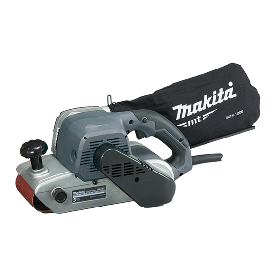
Page 1: Belt Sander
OFFICIAL USE For ASC Belt Sander M9400G REPAIR MANUAL... -
Page 2: Table Of Contents
CONTENTS CONTENTS ....................................2 CAUTION ....................................3 NECESSARY REPAIRING TOOLS ............................3 LUBRICANT AND ADHESIVE APPLICATION ........................3 REPAIR ......................................4 Armature ....................................4 5-1-1 Disassembling ................................4 5-1-2 Assembling .................................. 6 Driving Roller ..................................7 5-2-1 Disassembling ................................7 5-2-2 Assembling .................................. -
Page 3: Caution
Poly V-belt 6-355 Nut spinner handle (Square drive: 12.7 mm) disassembling Driving roller LUBRICANT AND ADHESIVE APPLICATION Apply the following lubricants and adhesives. Lubricant Amount Makita grease N No.2 a little Lubricating oil VG46 Fig. 1 Gear room Helical gear 42 complete... -
Page 4: Repair
REPAIR Armature 5-1-1 Disassembling Remove Brush holder caps and Carbon brushes. Fig. 2 Fig. 3 Remove M4x18 (+) Pan head screw, and remove Insert Lock nut wrench 28 between Poly V-belt Belt cover. 6-355 and Motor housing complete. And then pry up the wrench while turning V-pulley 6-52.9. - Page 5 Fig. 5 Fig. 6 Remove M4x45 (+) Pan head screw and four 4x40 Remove M5x12 (+) Pan head screw, and remove Fan Tapping screws, and remove Dust collector cover. 80. And then, separate Dust collector bracket And then, remove Separator. together with Armature from the machine by loosening two 4x18 Tapping screws.
-
Page 6: Assembling
Assembling Fig. 9 Hook Poly V-belt 6-355 completely with V-pulley 6-23. Set two spikes of Lock nut wrench 28 to the holes of V-pulley 6-52.9. While pressing the Poly V-belt 6-355 with your finger, turn V-pulley 6-52.9 with Lock nut wrench 28 counterclockwise. -
Page 7: Driving Roller
Driving Roller 5-3-1 Disassembling Remove Belt cover and Poly V-belt 6-355. (Refer to Fig. 2 and Fig. 3.) Fig. 10 Fig. 11 Remove three M4x18 (+) Pan head screws, and Remove two M4x18 (+) Pan head screws, and remove Gear cover section* from the machine. remove Safety cover. -
Page 8: Assembling
Fig. 13 Attach Socket 24-45 to Nut spinner handle. And fit the Socket to the hex portion of Driving roller. And then remove Driving roller by turning the hex portion of Driving roller clockwise. Driving roller Nut spinner handle Hex portion of Driving roller Socket 24-45 5-3-2... -
Page 9: V-Pulley 6-52.9, Helical Gear 10
V-pulley 6-52.9, Helical gear 10 5-4-1 Disassembling Disassemble Gear cover section. (Refer to Fig. 10.) Fig. 14 Fix Helical gear 10 of Gear cover section in Vise. Vise 1R041 Helical gear 10 Fig. 15 Insert the two spikes of Lock nut wrench 28 into the holes on V-pulley 6-52.9. And then, remove V-pulley 6-52.9 and Helical gear 10 by turning Lock nut wrench 28 counterclockwise. -
Page 10: Circuit Diagram
Circuit diagram Fig. 16 Insulated terminal Non-insulated for M3.5 screw terminal Black/AWG18 Switch White/AWG20 Field Brown/Black Black/AWG18 Black/AWG18 View from Fan side Terminal block (Closed end splice Power supply cord for some countries.) Blue/White Noise suppressor (If it is used.) Circuit of Switch AWG: American wire gauge 10 / 12... -
Page 11: Wiring Diagram
Wiring diagram Fig. 17 Assemble Field as shown below. Field lead wire Field Motor housing 11 / 12... - Page 12 Fig. 18 Field lead wire Hole Pass Field lead wires through the hole. Fix Field lead wires in Lead wire holders. Pass Field lead wires through this groove. Switch Groove Lead wire holder Terminal block (If it is used.) Noise suppressor (If it is used.) 12 / 12...
Need help?
Do you have a question about the M9400G and is the answer not in the manual?
Questions and answers