Table of Contents
Advertisement
Quick Links
Advertisement
Table of Contents

Subscribe to Our Youtube Channel
Summary of Contents for Imlab IKA VC 10
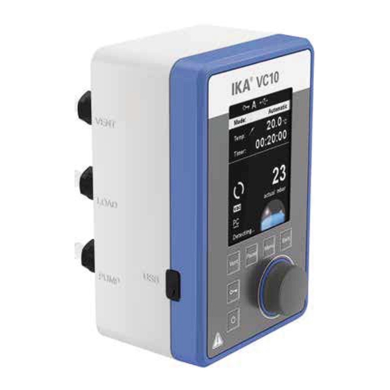
- Page 1 20000010677 VC 10_012017 ® VC 10...
-
Page 2: Table Of Contents
Source language: German Contents Page Device setup Declaration of conformity Explication of warning symbols Warranty Safety instructions Unpacking Correct use Useful information Setting up Commissioning Interfaces and outputs Maintenance and cleaning Error codes Accessories Product contact parts Technical data Declaration of conformity We declare under our sole responsibility that this product corresponds to the regulations 2014/35/EG, 2014/30/EG and 2011/65/ EG and conforms with the standards or standardized documents EN 61010-1, EN 60529, EN 61326-1 and EN ISO 12100. -
Page 3: Safety Instructions
Safety instructions For your protection Read the operating instructions in • The IKA ® VC 10 vacuum controller may only be operated NOTICE full before starting up and follow the under the conditions described in the “Technical data” safety instructions. chapter. -
Page 4: Unpacking
Unpacking Unpacking • Please unpack the device carefully. • In the case of any damage a detailed report must be sent immediately (post, rail or forwarder) Delivery scope Vacuum hose 1 m Vacuum controller IKA ® VC 10 Universal plug-in power Fig. - Page 5 Two-position control pump (rotation speed), the tightness of the system and signal de- A vacuum is made in the glassware with the help of a vacuum lay time of the electronics used. pump. The vacuum pump operates at constant speed which gene- Automatic boiling point recognition is not possible when using rally cannot be adjusted.
-
Page 6: Setting Up
Setting up Observe the general information, NOTICE d=16 mm always connect recipients (load/vacuum vessel/glass cooler) at their highest points to the suc- tion line. This will prevent the risk of fluid entering into the vacuum controller or pump. Install a separator (e.g. Woulff bottle) infront of the intake moun- ting to protect against the ingress of liquid. - Page 7 Connecting the interfaces P: PT 1000 temperature sensor Connect the vacuum hoses, pay attention to the following con- nections (also see Fig. 1): Connect the optional IKA ® PT 1000.60, PT 1000.61 or 1000.70 PT temperature sensor (accessory). The measured temperature (e.g. J: Load tempering bath) is shown on the display.
- Page 8 Illustration two-position control - vacuum pump/vacuum source with vacuum controller IKA ® VC 10 Vacuum source with two IKA ® VC 10 vacuum controllers. Once the target value is reached in a recipient, the suction line is For pumps which have the speed setting option, it is recommen- closed by the vacuum valve integrated in the IKA ®...
-
Page 9: Commissioning
Speed control ® MVP 10 digital vacuum pump with IKA VC 10 vacuum controller Automatic adjustment of the “analog speed control” mode if the cally reduced to a minimum “0 rpm”. Once the target value is analogue connection cable (Pos. 8) is connected to the pump with reached, the pump operates according to the leakage rate of the the vacuum controller. - Page 10 The following working screen appears automatically in the display. Display of two-position control, e.g. with IKA ® MVP 10 basic. Display speed control: IKA ® VP 10 digital to analogue connection Hysteresis display for two-position control No hysteresis display for speed control Explanation of symbols on the working screen The symbols displayed change depending on the status and set- tings of the vacuum controller:...
- Page 11 Navigation menu Press the "Menu" key (C). Select the menu by turning the rotating/pressing knob (D) to the right or left to select the desired menu or sub-menu, which can then be selected by pressing the rotating/pressing knob (D). Press or turn the rotating/pressing knob (D) again to select the desired menu option and edit the values or settings, or activate/ deactivate a function.
- Page 12 Menu structure Factory setting Menu Sub menu Option Action Deactivated Pump Modes Automatic..........................Activated Manual..........................Deactivated Pump %..........................Deactivated Program..........................05:00 [mm:ss] Cleaning Start after........................... 06:00 [mm:ss] Duration..........................20 % Pump speed......................... Deactivated Clean now...........
- Page 13 Menu details Pump Modes Pump % By selecting the “Pump %” menu item, the pump can be operated continuously with a running performance of between 100 % and 1 %. Program Under the “Programs” menu, 10 user-defined pressure-time profi- les can be created. The last measurement taken can also be view- ed in this menu and saved as a program.
- Page 14 Limits In this menu, limits for the target value can be set. Hysteresis With the “Hysteresis” option, the switching frequency and control accuracy can be influenced when in a steady state. The hysteresis value determines the upper and lower limits of the target value and therefore the closing and opening of the pump and valve (only for two-position control).
- Page 15 Temperature Temperature sensor In the ”Temperature” menu the user can specify that the tem-pera- ture sensor is displayed on the display/working screen. A tick ( ) shows that the option is activated. The precondition for this is that a temperature sensor is connec- ted to the vacuum controller.
- Page 16 Operating mode Operating mode A: In this operating mode, the set target value is not saved when the current run comes to an end or the device is switched off. Operating mode B: In this operating mode, the set target value is saved when the current run comes to an end or the device is switched off, and the value can be changed.
- Page 17 Details for editing the program In this program, user can define up to 10 segments. The selected segment is highlighted. Then, the user can edit, delete or insert a segment in this program. The program is save automa- tically. Edit: If the background of a selected value is yellow, the user can change the setting of the pressure value or the time value.
- Page 18 Safety In the “Password“ menu, the user can protect the vacuum cont- roller settings using a password. (factory setting: 000) Service In the “Service” menu, the valves and the pump can be operated individually and also checked to ensure that they are operating correctly.
-
Page 19: Interfaces And Outputs
Interfaces and outputs The device can be operated in “Remote” mode via an RS 232 or The above details correspond as far as possible to the recommen- ® USB interface using the laboratory software labworldsoft dations of the NAMUR working party (NAMUR recommendations for the design of electrical plug connections for analogue and The RS 232 interface at the back of the device is fitted with a digital signal transmission on individual items of laboratory control... -
Page 20: Maintenance And Cleaning
PC 1.1 Cable (Device to PC) Required for connecting the 9-pin socket to a PC. RxD 2 2 RxD TxD 3 3 TxD GND 5 5 GND RTS 7 7 RTS CTS 8 8 CTS Fig. 10 Connection VC 10 - PC 9-pin RS 232 9-pin RS 232 USB A... -
Page 21: Error Codes
Error codes Error: The fault is shown by an error message in the display as following if the error occurs, e.g. Error 4. Proceed as follows in such cases: • Switch the device switch off, • carry out corrective measures, •... -
Page 22: Accessories
Description Detection Reason Action Warning Temperature calibration value is out Wrong simulator resistance is chosen. Check the simulator resistance. of range. Set wrong temperature calibration Call service department. Temperature Calibration value. Error Pressure calibration value is out of Input wrong vacuum actual value Calibrate again. -
Page 23: Technical Data
Technical data Unit Value Connection diameter suction side Connection diameter pressure side Connection diameter venting side Gas ballast valve Input pressure min. mbar Input pressure max. mbar 1050 Boiling point detection Solvent library Two-point control Analog speed vacuum control Display Pressure unit / scale mbar, hPa, mmHg, Torr Vacuum sensor... - Page 24 Unit Value Dimensions (B x H x T) 95 x 150 x 110 Weight Permissible ambient temperature min. °C Permissible ambient temperature max. °C Permissible relative humidity Protection class according to DIN EN 60529 IP 20 RS 232 interface USB interface Analog output Voltage 100 - 240...
Need help?
Do you have a question about the IKA VC 10 and is the answer not in the manual?
Questions and answers