Table of Contents
Advertisement
SERVICE MANUAL
COOKING AND HOLDING SYSTEM with Pc board HSH - HSW -
HHT - HHB - CSC - CSD ...E models
LEGEND:
4 KEYS PC BOARD OPERATIONS 4 KEYS ...................................................................................................................2
4 KEYS PC BOARD DIAGNOSTICS.................................................................................................................................3
8 KEYS PC BOARD OPERATIONS 4 KEYS ...................................................................................................................4
8 KEYS PC BOARD DIAGNOSTICS.................................................................................................................................5
SUMMARY OF POSSIBLE MALFUNCTIONS....................................................................................................6
-
Replacing cavity heating element.......................................................................................................8
-
Replacing cavity temperature probe...................................................................................................11
-
Replacing heating element probe......................................................................................................13
-
Replacing core probe (only model with 8 keys pc board)........................................................................16
-
Replacing Pc board.......................................................................................................................18
-
Setting Pc board parameters...........................................................................................................20
-
Replacing general fuse....................................................................................................................20
RESEARCH AND DEVELOPMENT
1
Ed.1114
Advertisement
Table of Contents

Subscribe to Our Youtube Channel
Related Manuals for Moduline HSH E Series

Summary of Contents for Moduline HSH E Series
-
Page 1: Table Of Contents
RESEARCH AND DEVELOPMENT SERVICE MANUAL Ed.1114 COOKING AND HOLDING SYSTEM with Pc board HSH – HSW – HHT – HHB – CSC – CSD …E models LEGEND: 4 KEYS PC BOARD OPERATIONS 4 KEYS ………….......................2 4 KEYS PC BOARD DIAGNOSTICS………........................3 8 KEYS PC BOARD OPERATIONS 4 KEYS ………….......................4 8 KEYS PC BOARD DIAGNOSTICS…………........................5 SUMMARY OF POSSIBLE MALFUNCTIONS…………………………………..…………………………………………...6... -
Page 2: Keys Pc Board Diagnostics
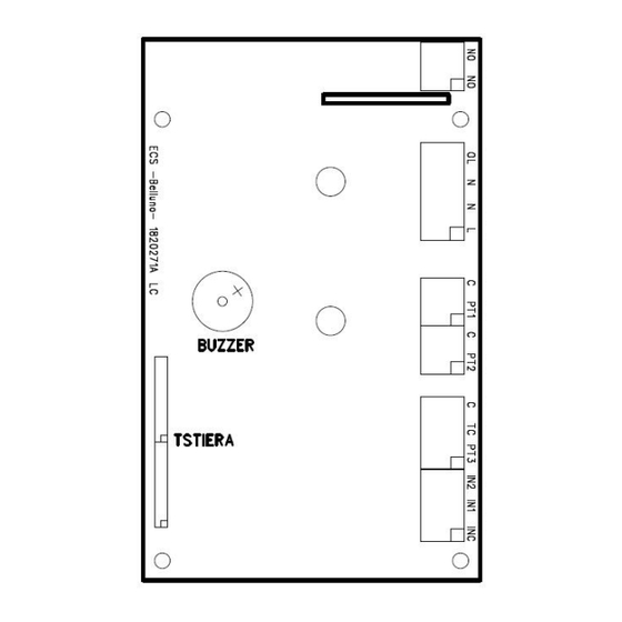
RESEARCH AND DEVELOPMENT 4 KEYS PC BOARD POWER SUPPLY Description Type Name N - L Power supply 230Vac LINE IN – NEUTRAL IN PROBE Description Type Conversion Range of use Probe Operating Range Range -50°C ÷ +500°C -25°C ÷ +400°C -20°C ÷... - Page 3 RESEARCH AND DEVELOPMENT You can reach this status by pressing the START/STOP key for long while in the OFF status. The display shows the chamber probe code “SCA”. By pressing the UP and DOWN keys, you pass to the heating element probe “SrE”. Pressing START/STOP displays the value read by the indicated probe;...
-
Page 4: Keys Pc Board Diagnostics
RESEARCH AND DEVELOPMENT 8 KEYS PC BOARD POWER SUPPLY Description Type Name N - L Power supply 230Vac LINE IN – NEUTRAL IN PROBE Description Type Conversion Range of use Probe Operating Range Range -50°C ÷ +500°C -25°C ÷ +400°C -20°C ÷... - Page 5 RESEARCH AND DEVELOPMENT DISPLAY STATUS AND PROBE TESTS You can reach this status by pressing the “CAVITY TEMPERATURE” key for long while in the OFF status. The display shows the chamber probe code “SCA”. By pressing the UP and DOWN keys, you pass to the heating element probe “SrE”...
-
Page 6: Summary Of Possible Malfunctions
RESEARCH AND DEVELOPMENT SUMMARY OF POSSIBLE MALFUNCTIONS Problem Probable cause Solution No electrical power Restore electrical power Power fuse blown Replace the blown power fuse The appliance does not Power cable not connected properly Check power cable connection switch on PC board faulty Replace PC board Check all electric connections inside... - Page 7 RESEARCH AND DEVELOPMENT Problem Probable cause Solution PC board faulty Replace PC board Cavity probe faulty Replace cavity probe The cavity heats up too much Heating element probe faulty Replace heating element probe Heating element probe in wrong Position heating element probe position correctly Cavity probe connected incorrectly...
-
Page 8: Failures And Relative Technical Interventions
RESEARCH AND DEVELOPMENT FAILURES AND RELATIVE TECHNICAL INTERVENTIONS Before proceeding with the intervention, make sure that the electric cable of the appliance is unplugged. Place the appliance on a flat and stable surface. - REPLACING CAVITY HEATING ELEMENTS To replace the cavity heating elements, proceed as follows: 1) For machine with door disassemble the door by unscrewing and removing the screw of the hinge highlighted in the photo at the bottom of the machine. - Page 9 RESEARCH AND DEVELOPMENT 3) Unscrew the 2 screws blocking the control panel and disassemble the board as described in the paragraph “replacing PC board” concerning failures and relative technical interventions. 4) Place the machine on its side in order to be able to unscrew the screws at the bottom. Bottom machine 5) Place the machine back in the correct position and remove the upper and side sheet steel cover, making sure not to pull the electric wires.
-
Page 10: Replacing Cavity Temperature Probe
RESEARCH AND DEVELOPMENT Heating element terminals 7) Remove the heating element and mount the new one respecting the previous positioning. Pay special attention to bend it carefully when positioning it in the curves in order not to ruin its insulation. If the heating element is longer than necessary, cut it to measure sheathing the end parts. - Page 11 RESEARCH AND DEVELOPMENT To replace the cavity temperature probe, proceed as follows: 1) For machine models with door disassemble the door by unscrewing and removing the screw of the hinge highlighted in the photo at the bottom of the machine. When the screw has been removed, the hinge and relative pin will slip off without problems and consequently the door as well.
- Page 12 RESEARCH AND DEVELOPMENT 4) Place the machine on its side in order to be able to unscrew the screws at the bottom. Bottom machine 5) Place the machine back in the correct position and remove the upper and side sheet steel cover, making sure not to pull the electric wires.
-
Page 13: Replacing Heating Element Probe
RESEARCH AND DEVELOPMENT 7) Mount the new cavity probe placing the brass nosepiece between the brass threaded closing fitting and the bush welded to the cavity. Brass nosepiece Brass threaded 8) Reposition the thermal insulation and close the machine by repeating the operations described in points 1-2-3-4-5 in the opposite order. - Page 14 RESEARCH AND DEVELOPMENT For models with drawers pull the drawers from the machine. 2) Unscrew the screws at the back of the machine and remove the closing panel. Also unscrew the 2 screws on the front of the appliance below the front control panel. Back of the machine Front of the machine 3) Unscrew the 2 screws blocking the control panel and disassemble the board as described in...
- Page 15 RESEARCH AND DEVELOPMENT Bottom machine 5) Place the machine back in the correct position and remove the upper and side sheet steel cover, making sure not to pull the electric wires. Then remove the thermal insulation without breaking it. 6) Unscrew the bracket securing the heating element probe and pull it off. Position the new heating element probe and remount the anchoring bracket.
-
Page 16: Replacing Core Probe (Only Model With 8 Keys Pc Board)
RESEARCH AND DEVELOPMENT Point of contact 7) Reposition the thermal insulation and close the machine by repeating the operations described in points 1-2-3-4-5 in the opposite order. - REPLACING CORE PROBE (ONLY MODEL WTH 8 KEYS PC BOARD) To replace the core probe, proceed as follows: 1) Disassemble the door by unscrewing and removing the screw of the hinge highlighted in the photo at the bottom of the machine. - Page 17 RESEARCH AND DEVELOPMENT Back of the machine Front of the machine 3) Unscrew the 2 screws blocking the control panel and disassemble the board as described in the paragraph “replacing PC board” concerning failures and relative technical interventions. 4) Place the machine on its side in order to be able to unscrew the screws at the bottom. Bottom machine 5) Place the machine back in the correct position and remove the upper and side sheet steel cover, making sure not to pull the electric wires.
-
Page 18: Replacing Pc Board
RESEARCH AND DEVELOPMENT 6) Unscrew the threaded nut which secures the core probe to the cavity. Then pull the probe out of the cavity. Mount the new core probe making sure to apply silicon between the cavity and flat washer placed before the threaded locking nut. To guarantee correct drying and sealing of the silicon, wait 24 hours before switching the machine on and heating the cooking chamber. - Page 19 RESEARCH AND DEVELOPMENT 2) Pull out the control panel with the relative PC board first from below as highlighted below. 3) Disconnect the wires connected to the various terminals of the PC board, taking note of their connection beforehand. Heating Cavity temperature element probe probe...
-
Page 20: Setting Pc Board Parameters
Despite the fact that whenever a new product is installed it already has its own specific parameters settled, at times they must be reconfigured. In order to receive the specific parameters and the procedures to be followed to set them, refer to the Moduline Technical Assistance Service specifying the serial number of the appliance. - Page 21 RESEARCH AND DEVELOPMENT 2) Pull out the control panel with the relative PC board first from below as highlighted below. 3) Remove the blown working fuse and insert the new fuse. 4) Close the appliance repeating the operations described in points 1-2 in the opposite order. Order a new fuse with the same technical data as the blown one to have it available for a future replacement.
Need help?
Do you have a question about the HSH E Series and is the answer not in the manual?
Questions and answers
Weird noise when running