Table of Contents
Advertisement
Available languages
Available languages
Quick Links
Advertisement
Chapters
Table of Contents

Related Manuals for RDZ DHW

Summary of Contents for RDZ DHW
- Page 1 Chiller and Heat Pumps Chiller e pompe di calore DHW CONTROL UNIT QUADRO GESTIONE ACS Control unit for Domestic Hot Water production with heat pump system Centralina di controllo della produzione di ACS con pompa di calore TECHNICAL MANUAL MANUALE TECNICO...
- Page 3 OPERATING AND INSTALLATION INSTRUCTIONS Control unit for domestic hot water production with heat pump system...
-
Page 4: Table Of Contents
DECLARATION OF CONFORMITY This product is marked as it satisfies Directives: • CEI EN 61000-6-1 (2007) Immunity for residential, commercial and light-industrial environments • CEI EN 61000-6-3 (2007) Emission standard for residential, commercial and light-industrial environments • CEI EN 60730-1 (2013) following DIRECTIVE 2014/30/EU + 2014/35/EU + 2011/65/EU This declaration will become void in case of misuse and/or non observance though partial of manufacturer’s installation and/or operating instructions . - Page 5 For the installer or service perso nit is important to install or service the system so that it operates safely and efficently. To start the warranty, the product must be started by an RDZ S.p.A service centre. Reccomandations • The personnel responsible for receiving the unit must conduct a visual inspection in order to identify all damage to witch the unit may have been duringl transport .
- Page 6 WARNING ELECTRICAL SHOCK CAN CAUSE SEVERE PERSONAL INJURY OR DEATH. ONLY A QUALIFIED, EXPERT ELECTRICIANS SHOULD ATTEMPT TO WIRE THIS SYSTEM. • Do not supply power until all wiring and tubing are completed or reconnected and checked,to ensure the grounding. •...
-
Page 7: Installation
1 INSTALLATION 1.1 GENERALITIES DHW Controller (or “control unit”) is a control and management device for domestic hot water production used with HP Heat Pump units. The control unit can drive an heat pump and an electric resistor (until 4 kW) to manage the various function by optimizing the electrical consumption. -
Page 8: Additional Required Material (Not Supplied)
1.3 ADDITIONAL REQUIRED MATERIAL (NOT SUPPLIED) • N° 1 Low voltage RELE (Recirculation pump buffer) • Wiring: use insulated copper wires of type,section and lenght indicated in 1.6 • Cable Press 1.4 ELECTRICAL REQUIREMENT • Before the installation, be sure that the voltage of power supply is the same as the one indicated on the device •... -
Page 9: Wiring
1.6 WIRING Lift the transparent cover, unscrew the two side screw and remove the cover. There are a PTR10 connector, seven FASTON, six grouping and one separated for grounding, a magnetothermic switch with output prewired to the unit and one prewired protection fuse for the electric resistor. PTR 10 terminal block •... -
Page 10: Wiring Diagram
1.7 WIRING DIAGRAM... -
Page 11: Startup
CABLES: LENGHT AND SECTION S(mm²) S(mm²) S(mm²) 0.75 0.75 Power supply cable A: Multipolar electric cable; Cable ‘s section is indicated in the above table . Cable must be H07RN-F type (CEI 20-19 CENELEC HD22). Make sure that the length of the wires between the cable fixing point and the terminals is such that the active conductors are tended before the grounding conductor . -
Page 12: Functional Diagram
1.9 FUNCTIONAL DIAGRAM... -
Page 13: Operating Instructions
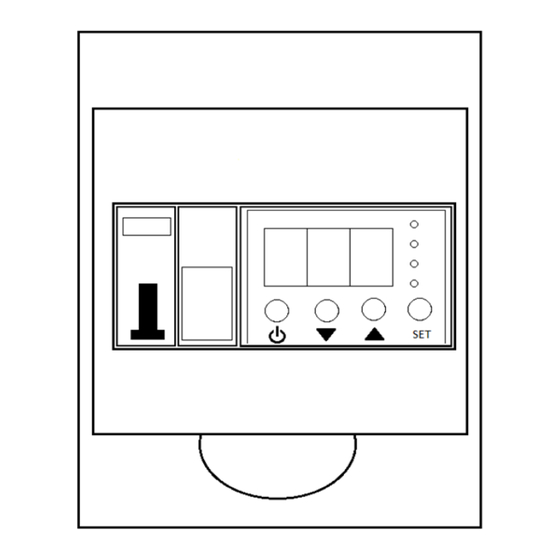
Switch ON / OFF the DHW Controller To turn on DHW Controller, press and hold the on-OFF button for two seconds until the red led turns off and the green LED lights up. The DHW Controller unit is designed to stay on continuously. -
Page 14: Parameters Setup
2.3 PARAMETERS SETUP USER ACCESS: Press the "SET" button for a brief moment to access the level 1 parameters TECHNICAL ACCESS: Press the “SET” button for 2 seconds (access the Password entry page); Use “UP” and “DOWN” to select characters, use “SET” to confirm the actual character and place the cursor at the next position. - Page 15 P.20 Operation mode 0 = OFF: Heating OFF (but protections ON) 1 = ECO: Only heat pump 2 = SMART: Heat pump plus integration resistor if the pump is not enough 3 = FAST: Heat pump + resistor together active 4 = BACKUP: Only resistor P.22 SMART ENERGY enabling...
- Page 16 P.63 Protocollo variant 1 = Standard 2 = Special P.70 Minimum temperature curve °C See section 3.3 killing Legionella P.71 Killing time at minimum See section 3.3 temperature P.72 Average temperature curve killing °C See section 3.3 Legionella P.73 Killing time at average See section 3.3 temperature P.74...
-
Page 17: Diagnostic Table
2.5 DIAGNOSTIC TABLE ERROR CAUSE LOGGED DISPLAY No ‘NET SYNC’ signal. Replace on board fuse Temperature derivative insufficient Only if P.82=1 RS485 network error (future use) Tank temperature higher than T max (P.54) Tank temperature probe CC or disconnected Recirculating temperature probe CC or disconnected Only if P.51=1 Only if P.51=1 SETUP data error... - Page 18 Manual starting anti-Legionella cycle DWH Controller performs an automatic check to determine if it is necessary to initiate the anti-Legionella cycle according to the procedure in section 3.3. However, you can manually start the loop by entering the configuration menu, moving to parameter P. 04 and pressing the SET button. In this way it is forced to start the cycle and the control unit goes back to the main page.
-
Page 19: Features
3 FEATURES 3.1 DOMESTIC HOT WATER PRODUCTION The control parameters of this feature are: P.01 Desired Set-point P.20 Operating mode P.20=0 OFF: Domestic hot water production disabled P.20=1 ECO: Production with only heat pump P.20=2 SMART: Production with heat pump + electric resistor by minimizing power consumption P.20=3 FAST: Production with heat pump + electric resistor by minimizing working time P.20=4 BACKUP: Production with only electric resistor P.57 Tank temperature hysteresis... -
Page 20: Recirculation Management
3.2 RECIRCULATION MANAGEMENT The Recirculating function allows you to enter the DHW circuit at the desired operating temperature. This reduces the waste of water that occurs when a withdrawal occurs while waiting for the desired temperature to reach a comfortable value. -
Page 21: Anti-Freeze Management
3.4 ANTI-FREEZE MANAGEMENT If the control unit is turned on in the standby state, it is possible to activate the anti-freeze function (parametro P.02). If the water temperature in the tank falls below 5.0 °C, the control unit activates all available heat sources until the temperature rises above 10 °C. - Page 23 MANUALE D'USO E INSTALLAZIONE Centralina di controllo della produzione di acqua calda sanitaria con pompa di calore...
- Page 24 DICHIARAZIONE DI CONFORMITÀ Questo prodotto è marcato in quanto conforme alle Direttive: • CEI EN 61000-6-1 (2007) Immunity for residential, commercial and light-industrial environments • CEI EN 61000-6-3 (2007) Emission standard for residential, commercial and light-industrial environments • CEI EN 60730-1 (2013) following DIRECTIVE 2014/30/EU + 2014/35/EU + 2011/65/EU Questa dichiarazione sarà...
- Page 25 Per l’installatore o il personale di assistenza è molto importante installare o riparare il sistema di modo che quest’ultimo operi con sicurezza ed efficienza. Per dare inizio alla garanzia, il prodotto dovrà essere avviato da un centro assistenza RDZ S.p.A. Raccomandazioni •...
- Page 26 AVVERTIMENTO LA SCARICA ELETTRICA PUO’ CAUSARE LESIONI MOLTO GRAVI O LA MORTE. SOLO ELETTRICISTI QUALIFICATI ED ESPERTI POSSONO MANIPOLARE IL SISTEMA ELETTRICO. • Non alimentare l’unità finché tutti i cavi e i tubi non siano completati o ricollegati e controllati, per assicurare le messa a terra.
-
Page 27: Installazione
1 INSTALLAZIONE 1.1 GENERALITA’ DHW Controller (o “centralina”) è un dispositivo di controllo e gestione della produzione di acqua calda sanitaria per sistemi con Pompe di calore monoblocco HP. L’unità di controllo è in grado di pilotare una pompa di calore e una resistenza elettrica (fino a 4 kW) tramite le quali riuscire a gestire le diverse funzionalità... -
Page 28: Materiale Addizionale Per L'installazione (Non Fornito)
1.3 MATERIALE ADDIZIONALE PER L’INSTALLAZIONE (NON FORNITO) • N° 1 Relè a bassa tensione (buffer per la pompa di ricircolo) • Cavo elettrico: utilizzare cavi di rame isolato del tipo, sezione e lunghezza indicati al paragrafo 1.6Errore. L'origine riferimento non è stata trovata. •... -
Page 29: Collegamenti Elettrici
1.6 COLLEGAMENTI ELETTRICI Sollevare il coperchio trasparente, svitare le due viti laterali e rimuovere il coperchio. Sono presenti un connettore PTR dieci poli, sette FASTON, sei raggruppati e uno separato per la messa a terra, un interruttore magnetotermico con l’uscita precablata verso l’unità di controllo e un fusibile di protezione per la resistenza elettrica, precablato. -
Page 30: Schema Collegamento Elettrico
1.7 SCHEMA COLLEGAMENTO ELETTRICO... -
Page 31: Messa In Funzione
LUNGHEZZA E SEZIONE CAVI S(mm²) S(mm²) S(mm²) 0.75 0.75 Cavo di alimentazione A: Cavo elettrico multipolare; la sezione del cavo elettrico consigliato è indicata in tabella. Il cavo deve essere del tipo H07RN-F (secondo CEI 20-19 CENELEC HD22). Assicurarsi che la lunghezza dei conduttori fra il punto di fissaggio del cavo ed i morsetti sia tale che i conduttori attivi si tendano prima del conduttore di messa a terra. -
Page 32: Schema Funzionale
1.9 SCHEMA FUNZIONALE... -
Page 33: Istruzioni D'uso
(Es. “r11”) per due secondi, poi passa alla “schermata principale”, nella quale, alla prima accensione, nella quale il LED ROSSO è acceso e il display numerico è spento. Accensione / Spegnimento DHW Controller Per accendere Quadro Gestione ACS, tenere premuto il pulsante ON-OFF per due secondi, fino a quando si spegne il... -
Page 34: Impostazione Parametri
Per spegnere Quadro Gestione ACS, tenere premuto il pulsante ON-OFF per due secondi fino a quando si accende il LED ROSSO e si spengono gli altri. Lo stato di Accensione/Spegnimento viene mantenuto tra due accensioni consecutive. 2.3 IMPOSTAZIONE PARAMETRI ACCESSO UTENTE: Premere il tasto “SET”... - Page 35 P.12 Orologio: Regolazione giorno della 1 = Lunedì settimana … 7 = Domenica P.13 Orologio: Regolazione giorno del mese P.14 Orologio: Regolazione mese P.15 Orologio: Regolazione anno P.16 Frequenza ciclo anti-legionella Intervallo minimo in giorni tra due cicli anti-legionella. Impostare a 0 per disabilitare il ciclo anti-legionella.
- Page 36 P.57 Isteresi regolazione temperatura °C Vedi sezione 3.1 serbatoio P.58 Derivata minima temperatura °C 20.0 Aumento minimo della serbatoio temperatura del serbatoio calcolata su 60 minuti. Vedi sezione 3.1 P.59 Tempo di controllo della derivata Frequenza di calcolo della derivata per controllo derivata minima (P.58).
-
Page 37: Tabella Diagnostica
2.5 TABELLA DIAGNOSTICA ERRORE CAUSA REGISTRATO DISPLAY Segnale ‘SYNC RETE’ assente. Sostituire fusibile a bordo macchina Derivata della temperatura insufficiente Solo se P.82=1 Errore rete RS485 (uso futuro) Temperatura serbatoio inferiore a T max (P.54) Sonda Temperatura serbatoio in cortocircuito o scollegata Sonda Temperatura ricircolo in cortocircuito o scollegata Solo se P.51=1 Solo se P.51=1... - Page 38 Per attivare la modalità BOOST, dallo stato ON (LED ROSSO spento) premere per due secondi il tasto SU; a monitor appare l’indicazione “Bst” per due secondi, poi la funzionalità si attiva e viene visualizzata la temperatura dell’acqua nel serbatoio. Avvio manuale ciclo anti-legionella DWH Controller effettua un controllo automatico per determinare se è...
-
Page 39: Funzionalita
3 FUNZIONALITA’ 3.1 PRODUZIONE ACQUA CALDA SANITARIA I parametri di controllo di questa funzionalità sono: P.01 Set-point desiderato P.20 Gestione modalità di funzionamento: P.20=0 OFF: Termostatazione disabilitata P.20=1 ECO: Utilizzo solo la pompa di calore P.20=2 SMART: Pompa di calore + resistenza elettrica minimizzando il consumo elettrico P.20=3 FAST: Pompa di calore + resistenza elettrica minimizzando il tempo di lavoro P.20=4 BACKUP: Utilizzo solo resistenza elettrica P.57 Isteresi di regolazione temperatura serbatoio... -
Page 40: Gestione Ricircolo
3.2 GESTIONE RICIRCOLO La funzione ricircolo permette di immettere nel circuito ACS acqua alla temperatura di esercizio desiderata. Questa operazione consente di ridurre lo spreco di acqua che si verifica quando si verifica un prelievo in attesa che la temperatura desiderata raggiunga un valore confortevole. I parametri di controllo sono: P.51 Modalità... -
Page 41: Gestione Anti-Freeze
resistenza elettrica. In caso di disconnessione delle resistenze elettriche, in talune condizioni operative, potrebbe succedere che il ciclo anti-legionella non venga completato, condizione per la quale la nostra azienda non si assume alcuna responsabilità civile. 3.4 GESTIONE ANTI-FREEZE Nel caso in cui la centralina sia accesa nello stato di STAND-BY, è possibile attivare la funzione anti congelamento (parametro P.02). - Page 44 FAG0FC001AB.00 12/2018...
Need help?
Do you have a question about the DHW and is the answer not in the manual?
Questions and answers