Table of Contents
Advertisement
Contents
Mounting instructions
VacuStar W900 / W1300 / W1600
Doc-ID: 5004 / MA / EN
Release: Rev. 06 / 31.01.2018
Prior to installing the VacuStar W and putting it into operation you must have read and understood
these instructions. These instructions are only valid together with the operating instructions, they do
not replace them!
Advertisement
Table of Contents

Subscribe to Our Youtube Channel
Related Manuals for CVS VacuStar W Series

Summary of Contents for CVS VacuStar W Series
- Page 1 Contents Mounting instructions VacuStar W900 / W1300 / W1600 Doc-ID: 5004 / MA / EN Release: Rev. 06 / 31.01.2018 Prior to installing the VacuStar W and putting it into operation you must have read and understood these instructions. These instructions are only valid together with the operating instructions, they do not replace them!
- Page 2 Translation of the Original Assembly Instructions © CVS engineering GmbH Großmattstraße 14 79618 Rheinfelden / Germany Phone: +49 (0)7623 71741-0 Customer service: +49 (0)7623 71741-0 E-Mail: info@cvs-eng.de Internet: www.cvs-eng.de...
-
Page 3: Table Of Contents
Mounting instructions VacuStar W900 / W1300 / W1600 Contents General ..................5 Information on the assembly instructions ...... 5 Pictogram explanation ........... 6 Limitation of Liability ............7 Copyright protection ............7 Spare parts ..............7 Warranty conditions ............7 Customer Service ............ - Page 4 Mounting instructions VacuStar W900 / W1300 / W1600 Contents 6.11.1 Additional oil lubrication ........34 6.12 Drive ..............35 6.12.1 V belt drive ............36 6.12.2 Articulated shaft drive ........36 6.12.3 Drive via flexible coupling and hydraulic motor .............37 Start-up ..................37 Safety during start-up ...........37 Start-up ................38 Switching off ..............40 Inspections to be performed ........41...
-
Page 5: General
Mounting instructions VacuStar W900 / W1300 / W1600 General 1 General 1.1 Information on the assembly instructions These mounting instructions provide important information about installation and start-up of the VacuStar W. A precondition for safe operation is the observance of all specified safety and handling instructions. -
Page 6: Pictogram Explanation
Mounting instructions VacuStar W900 / W1300 / W1600 General 1.2 Pictogram explanation Warning notes Warning notes are characterised by pictograms in these mounting instructions. The warning notes are marked by signal words expressing the extent of the hazard. It is absolutely essential to observe the notes and to proceed with caution in order to prevent accidents as well as bodily injuries and property damage. -
Page 7: Limitation Of Liability
Mounting instructions VacuStar W900 / W1300 / W1600 General 1.3 Limitation of Liability Information regarding the limitation of liability can be found in the operating instructions "VacuStar W900 / W1300 / W1600". 1.4 Copyright protection Information regarding the copy right protection can be found in the operating instructions "VacuStar W900 / W1300 / W1600". -
Page 8: Safety
Mounting instructions VacuStar W900 / W1300 / W1600 Safety 2 Safety 2.1 Intended use The compressor vacuum pumps series VacuStar W were developed to be installed into a superior system. The manufacturer of the overall system must assess the new risks resulting from the installation. -
Page 9: Proper Operation
Mounting instructions VacuStar W900 / W1300 / W1600 Safety 2.2 Proper operation The proper operation is determined mainly by the following criteria: − 1 Drive speed range: 1000...1500 min maximum final temperature: 195 °C (T3) / 220 °C (T2) Ambient temperature: −20…+40 °C ... -
Page 10: Requirements Placed Upon The Specialised Staff
Mounting instructions VacuStar W900 / W1300 / W1600 Safety 2.5 Requirements placed upon the specialised staff The mounting instructions specify the following qualification requirements for the different fields of activity: Specialists are due to their technical training, knowledge and experience and their knowledge of the pertinent regulations able to carry out the work assigned to them and to independently recognize potential hazards. -
Page 11: Technical Data
Mounting instructions VacuStar W900 / W1300 / W1600 Technical data 3 Technical data 3.1 Dimensions of the VacuStar W900 / W1300 / W1600 Fig. 1: Dimensions of VacuStar W VacuStar W900 W1300 W1600 1027 Suction flange, pressure flange, connection for tank vehicle flange (DN 125) as per DIN 28461 Tab. -
Page 12: Technical Data
Mounting instructions VacuStar W900 / W1300 / W1600 Technical data 3.2 Technical data VacuStar W operating data Model Model Model Unit W900 W1300 W1600 –1 Rated speed / speed range [min 1500 / 1000…1500 Nominal operating vacuum [mbar] Permanent operating vacuum with cell ventilation [mbar] Permanent operating vacuum without cell [mbar]... - Page 13 Tab. 5: Lubricating oils Recommended oil types Brand Suction temp. > 10 °C Suction temp. < 10 °C CVS Lube 4000 CVS Lube 3000 Other oil types on request. Tab. 6: Lubricating oil types ATTENTION! Do not use any synthetic lubricants!
-
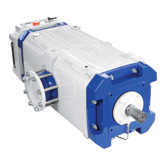
Page 14: Design
Mounting instructions VacuStar W900 / W1300 / W1600 Design 4 Design 4.1 Design Fig. 2: View VacuStar W and details Negative pressure connection Centring device and fastening Connection cell ventilation (R 2“) (R 3/8“) of hydraulic motor mounting Oil level indicator (bilateral) flange 14 Suction connection Crank for manual lubrication... - Page 15 Mounting instructions VacuStar W900 / W1300 / W1600 Design Cooling The VacuStar W is water-cooled. The VacuStar W is equipped with a cooling jacket inside the casing. An external circulation cooling with an air-cooled cooler is necessary for the return of the cooling water. See page 32.
-
Page 16: Transport And Storage
Mounting instructions VacuStar W900 / W1300 / W1600 Transport and storage 5 Transport and storage 5.1 Safety notes for transport Improper transport Danger! Danger by falling down or tilting of the VacuStar W! The weight of the VacuStar W may injure a person and cause serious bruising! Therefore: –... -
Page 17: Storage
Mounting instructions VacuStar W900 / W1300 / W1600 Transport and storage 5.3 Storage Storage of packages Store packages under the following conditions: Do not store outdoors. Store dry and dust free. Do not expose to aggressive media. ... -
Page 18: Installation And Assembly
Mounting instructions VacuStar W900 / W1300 / W1600 Installation and assembly 6 Installation and assembly 6.1 Safety Safety WARNING! Risk of explosion! Only use components that are suitable for the zone in which the unit is used when you install the unit in an explosive atmosphere. -
Page 19: Installation Example
Mounting instructions VacuStar W900 / W1300 / W1600 Installation and assembly 6.2 Installation example The illustration shows an example of a system with an installed VacuStar W. Fig. 3: Installation of the VacuStar W (example) Vehicle tank 10 Cell ventilation filter 18 Ventilating valve Safety dome 11 Sound absorber - oil... -
Page 20: Necessary Work
Mounting instructions VacuStar W900 / W1300 / W1600 Installation and assembly NOTE! For the water circuit, see chapter 6.11! 6.3 Necessary work The following work is necessary to install the VacuStar W: Install all vehicle components such as oil separators, collection containers, etc. -
Page 21: Installing Vacustar W
Mounting instructions VacuStar W900 / W1300 / W1600 Installation and assembly 6.5 Installing VacuStar W The VacuStar W is attached to the bottom of the VacuStar W with 4 attachment points. Checking the function before the Check the rotor shaft function. Rotating the rotor shaft with your installation hand must be possible. -
Page 22: Compensators
Mounting instructions VacuStar W900 / W1300 / W1600 Installation and assembly 6.6 Compensators Compensators for the On the suction side, compensators with Teflon lining and vacuum suction and pressure lines support ring should be used. On the pressure side, you must ensure pressure resistance, overpressures of up to 2.0 bars and temperature resistance up to 240 °C. -
Page 23: Safety Valve (Overpressure Protection)
Mounting instructions VacuStar W900 / W1300 / W1600 Installation and assembly 6.8.1 Safety valve (overpressure protection) Risk of explosions DANGER! Risk of injury by explosions! Explosions can cause severe injuries! Therefore: – Install the safety valve as instructed. Observe the manufacturer's instructions. –... -
Page 24: Ventilation Valve (Vacuum Protection)
Install the ventilation valve on the suction side of the VacuStar W. Set minimum permissible vacuum: − for system without cell ventilation: 200...1000 mbar − for system with cell ventilation: 100…1000 mbar. NOTE! The ventilation valve can be procured from CVS! -
Page 25: Monitoring The Compression End Temperature
Mounting instructions VacuStar W900 / W1300 / W1600 Installation and assembly 6.8.3 Monitoring the compression end temperature The final temperature of the VacuStar W must be monitored. A suitable measuring instrument must be installed that switches the VacuStar W off when the maximum permissible temperature is reached. -
Page 26: Non-Return Valve
Install the vacuum filter into the suction line upstream from the VacuStar W. Observe the flow direction. ATEX note For explosion-proof VacuStar W, use only filters that are resistant to the explosion pressure shock. Such filters can be purchased from CVS. -
Page 27: Protection Against Contact
Check the full stroke. Full stroke = 27 mm. ATEX note When transporting explosive gases and gas mixtures, the control and fresh air lines must be explosion and shock-proof (11.6 barg). Cell ventilation valve, muffler and suction filter can be purchased from CVS... - Page 28 Mounting instructions VacuStar W900 / W1300 / W1600 Installation and assembly Fig. 5: Cell ventilation valve with muffler and air filter Air filter (installed vertically) Hose adapter Muffler (installed horizontally or vertically) Muffler holder Connection line, max. length 1 m (not included in scope of delivery) Hose stub Cell ventilation valve (installed vertically)
-
Page 29: Shut-Off Valve In The Control Line
Mounting instructions VacuStar W900 / W1300 / W1600 Installation and assembly 6.8.8 Shut-off valve in the control line A shut-off valve must be installed in the control line in order to avoid reversing of the VacuStar W when the tank is evacuated at deactivation. -
Page 30: Display And Monitoring Equipment
Mounting instructions VacuStar W900 / W1300 / W1600 Installation and assembly 6.8.10 Display and monitoring equipment CAUTION! All display and monitoring devices in a system that is used for conveying explosive material must comply with the Directive 2014/34/EC (ATEX) with respect to equipment category, temperature class and explosion group. -
Page 31: 40B40Badditional Components Of The System
Mounting instructions VacuStar W900 / W1300 / W1600 Installation and assembly 6.9 40B40BAdditional components of the system 6.9.1 Sound absorber - oil separator Requirement The pressure resistance of the muffler separator must be adapted to the permissible system pressure. Assembly Install the muffler oil separator between the VacuStar W and the switch four way tap. -
Page 32: Cooling Water System
See 12, Tab. 4: Cooling water circuit. The following illustration shows a diagram of a cooling water circuit. Fig. 6: Diagram of cooling water circuit Cooling water inflow Cooling water outflow All components can also be purchased from CVS. - Page 33 Mounting instructions VacuStar W900 / W1300 / W1600 Installation and assembly Assembly Observe the following points during installation: Recommended cooling water cycling volume 5,200 l/h at 0.2 bar pressure loss Install the radiator stress-free on rubber elements. Install the cooling water pump at the lowest point.
-
Page 34: Additional Oil Lubrication
Mounting instructions VacuStar W900 / W1300 / W1600 Installation and assembly 6.11.1 Additional oil lubrication Additional lubrication in extreme With vehicles used in extreme conditions, additional lubrication operating conditions may be required. These are extreme operating conditions: Ambient temperature above 35 °C ... -
Page 35: Drive
Mounting instructions VacuStar W900 / W1300 / W1600 Installation and assembly 6.12 Drive CAUTION! Drive and coupling of a system that is used for conveying explosive material must comply with the Directive 2014/34/EC (ATEX) with respect to equipment category, temperature class and explosion group. -
Page 36: Belt Drive
Mounting instructions VacuStar W900 / W1300 / W1600 Installation and assembly 6.12.1 V belt drive ATTENTION! The maximum permissible lateral force on the shaft of the VacuStar W must not exceed 5300 N. Observe the design, installation and inspection instructions of the manufacturer. The following belt pulleys can directly be installed on the shaft end of the VacuStar W: VacuStar W V-belt drive... -
Page 37: Drive Via Flexible Coupling And Hydraulic Motor
The hydraulic motor is installed to the VacuStar W via an intermediate flange. The power is transmitted via a flexible coupling. Components that match the VacuStar W type can be ordered from CVS. Start-up 7.1 Safety during start-up Start-up, operation... -
Page 38: Start-Up
Mounting instructions VacuStar W900 / W1300 / W1600 Start-up 7.2 Start-up Inspection prior to initial start-up The following points must be checked prior to initial start-up: Inspect the VacuStar W and the entire system Check the pipes for continuity and residues (remove blanks if there are any) ... - Page 39 Mounting instructions VacuStar W900 / W1300 / W1600 Start-up Inspections during operation The following inspections have to be carried out during operation: Prior to every start-up and during operation, the oil level and the coolant level must be checked and topped up if necessary. ...
-
Page 40: Switching Off
Mounting instructions VacuStar W900 / W1300 / W1600 Start-up ATEX note The following points must be observed when explosive gases and gas mixtures are conveyed: Prior to every start of the VacuStar W and during operation: – Check coolant –... -
Page 41: Inspections To Be Performed
7.4 Inspections to be performed Lubricating oil inspection Only lubricating oils pursuant to the lubricants specifications on page 13 are approved for the VacuStar W series. The manual prelubrication of the VacuStar W is always required during the initial operation. -
Page 42: Ec Declaration Of Incorporation
Mounting instructions VacuStar W900 / W1300 / W1600 EC Declaration of Incorporation 8 EC Declaration of Incorporation... -
Page 43: Atex Declaration Of Conformity
Mounting instructions VacuStar W900 / W1300 / W1600 ATEX Declaration of Conformity 9 ATEX Declaration of Conformity... -
Page 44: Index
Mounting instructions VacuStar W900 / W1300 / W1600 Index Index Acceptance ............9 Non-return valve..........26 Additional oil lubrication ........34 Articulated shaft drive ........36 Occupational safety ........... 10 ATEX ........8, 25, 26, 27, 40, 41 Operator ............... 9 ATEX Declaration of Conformity ...... - Page 45 Mounting instructions VacuStar W900 / W1300 / W1600 Index...
Need help?
Do you have a question about the VacuStar W Series and is the answer not in the manual?
Questions and answers