
Related Manuals for Minipack-Torre MEDIA MATIC 50


Summary of Contents for Minipack-Torre MEDIA MATIC 50
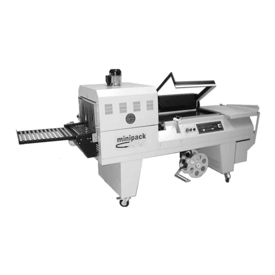
- Page 1 MEDIA MATIC 50 Instruction manual Before using the machine please carefully read the instructions...
- Page 2 УПАКОВОЧНОЕ ОБОРУДОВАНИЕ ПРОИЗВОДСТВО И ПОСТАВКА СЕРВИСНЫЙ РЕМОНТ ЗАПАСНЫЕ ЧАСТИ РАСХОДНЫЕ МАТЕРИАЛЫ Диагностика, ремонт, сервисное обслуживание. Запасные части и расходный материал: резина, тефлоновая лента, термонож (лезвие), гель для смазки. Плёнка термоусадочная полиолефиновая. Система «Trade-In» − замена Вашего оборудования на новое и более...
-
Page 3: Table Of Contents
Index Chapter 1. • Foreword 1.1. Introduction...…..…………... 1.2. Performances of packaging machine.…………… 1.3. Machine identification..……………………………. 1.4. Weight and dimensions of packed machine 1.5. Machine weight and dimensions..……….. Chapter 2. Machine installation 2.1. Transport and positioning.....….….………… 2.2. Environmental conditions...…..………... 2.3. Electrical connections.....….….………... Chapter 3. -
Page 4: Introduction
1.2. Performances of packaging machine “MEDIA MATIC 50” is an L-sealer packaging machine equipped with shrinking tunnel. Which represents a real novelty ab it is incorporate in machine structure. Such a tunnel is height and speed adjustable,equipped with temperature adjustment; the machine is more compact and versatile as it is included in its bodywork. -
Page 5: Machine Weight And Dimensions
a = mm 800 b = mm 2780 c = mm 1400 Peso = Kg 287 a = mm 900 b = mm 2500 c = mm 1500 Peso = Kg 343 1.5. Machine weight and dimensions Chapter2. Machine installation 2.1. -
Page 6: Environmental Conditions
Cut strap with scissors and remove the cardboard. Remove the cardboard containing the trolley (Y). Unscrew the 4 fastening screws of the pallet. Lift the machine by using a fork lift. Place the four wheels onto the machine. Remove the box (X) containing the closing panels and fix them to the legs. -
Page 7: Electrical Connections
Machine safety factor = IP32 The aerial noise made by the machine is lower than 70 dB 2.3. Electrical connections OBSERVE HEALTH AND SAFETY REGULATIONS! GROUNDING OF THE UNIT IS OBLIGATORY! Before executing electrical connections, make sure the mains voltage matches the one on the plate on machine rear and that the earthing contact complies with the safety rules in force. - Page 8 Chapter 3. Machine adjustment and setting up 3.1. Adjustment A - Main switch B - Sealing warning light Variables selection switch C - Warning light of belt advancing time Adjusting button D - Pause warning light Reset button E - Warning light of over belt speed Piece counter display F - Temperature warning light Emergency button...
- Page 9 3.1. Adjustment ELECTRONIC BOARD FEATURES The machine is equipped with 5 selection able programs: Program nr. Program features Cutting only Cutting + belt advancing (no shrinking) Complete program P3 - P4 - P5 Each program is composed by 6 variables which can be modified: Variable Field Field features...
-
Page 10: Manual And Automatic Cycle
N.B.: tunnel units (heating elements, fan, belt) are activated in programs P3-P4-P5. In any case they are not brought into operation soon after selecting above programs, but through a manual command. When selecting one of these programs, display will show ”L3” instead of “P3”;... -
Page 11: Film Roll Insertion
To operate the automatic cycle rotate the selector (Q) to the AUTOMATIC position and press the start button (P). The machine is equipped with an EMERGENCY BUTTON (O) which blocks it immediately when pressed, bringing the sealing frame into start position. The machine has also an automatic safety system on the welding frame which intervenes in case the lowering of the frame is hindered, bringing the frame back in the start position. -
Page 12: Air Flow Adjustment
Adjust the height belt acting on the proper handwheel. Adjust curtains acting placed on tunnel inlet on the proper knobs to get them at the same level of tunnel belt. 3.5. Air flow adjustment... -
Page 13: Film Roll Support And Packaging Plate Adjustment
It is possible to adjust the air flow on the product to pack by acting on the knobs (7). The rotation of handles (7) determines the position of the flaps (8) which drive the hot air flow into the desired direction so to obtain the best shrinking. - Page 14 The film roll support (3) and the packaging plate (5) must be adjusted according to the width of the item to be packed, leaving about 1-2 cm between the item and the sealing edge. 3.7. Execution of 1^ film sealing To carry out the 1^ welding move the film, as shown in the figure.
-
Page 15: Film Coupler On Wrapping Machine
performed on the film’s left side. With the right hand detach the film from the sealing blade. 3.8. Film coupler on wrapping machine (where expected) Carry out a number of cycles sufficient to make a strip of scrap film. -
Page 16: Introducing The Object To Be Wrapped
Guide this film strip around the transmission roll (9) and the driving roll (10) and couple it with the coiler (11). The machine is now ready to start the packaging. 3.9. Introducing the object to be wrapped Lift film edge on the packaging plate with your left hand. - Page 17 Press the ON push-button (P). The welding frame will automatically lower to cut and weld the film. When the frame opens again, the packed product will be fed towards the tunnel. Thus, the welding area will be released and ready to start a new welding cycle.
-
Page 18: Band A Calculation
5.1. Films to be used Machine can work with all shrinkwrapping films with thickness 15-50 micron manufactured by ”MINIPACK- TORRE S.p.A.”. The special features of our films (which may be customized with drawings and text) assure their outstanding reliability, with regard both to compliance with laws in force and to an excellent machine performance. - Page 19 Do not touch the sealing blade (19) soon after sealing by reaching beyond the safety guard (12). Danger of burns due to residual heat on the sealing blade. Do not keep on sealing in case the sealing blade breaks (19). Replace it at once.
- Page 20 6.1. Warnings WARNING! Do not touch the machine hot components during the heating phase. Danger of burns! WARNING! Do not touch the transport belt while it is moving. Chapter 7. Ordinary maintenance...
-
Page 21: Sealing Blade Cleaning
7.1. Precautions for ordinary maintenance interventions BEFORE PROCEEDING TO MAINTENANCE, SWITCH THE MACHINE OFF AND DISCONNECT IT BY OPERATING ON THE MASTER SWITCH. 7.2. Sealing blade cleaning Using a dry cloth, wipe off the residues clinging to the sealing wire: do this at once after sealing since they are easier to remove when still warm. -
Page 22: Control Of Cooling Liquid
When the bobbin of the automatic coiler (15) is full, remove the film by unscrewing the knob (17) and taking away the disk (16) 7.4. Control of cooling liquid Check the level of the cooling fluid once every 6 months. To do so, remove the guard (R) and unscrew the plug (35). -
Page 23: Rubber And Teflon Replacement
7.5. Rubber and teflon replacement When the Teflon-stripes (13) are worn out, replace them with spare parts, paying attention that the application is linear and even. Before applying the teflon self- adhesive strip clean the rubber part (14) with a detergent. If also the rubber (14) is damaged too, replace it as follows:... -
Page 24: Changing The Sealing Wire
Cams adjustment must be carried out only by authorised personnel! Disassemble the panel (38) at the back of the machine to get access to the cams. The 2 cams are adjusting: 1. Sealing frame lowering and its pressure on the sealing blade. 2. - Page 25 To replace the sealing blade (19) follow this procedure: • Disconnect power to the machine • Unscrew the three screws (20), (21), (22) • Remove the old sealing blade • Clean the housing and if necessary replace the insulating teflon (23) of the central clamp •...
-
Page 26: Wiring Diagram
7.8. Wiring diagram... -
Page 28: Spare Parts
WIRING DIAGRAM DESCRIPTION QS1 Main switch Frame lowering limit switch EH1 Cutting resistance Frame lifting limit switch EH2 Oven resistors Safety device cutting out limit switch EH3 Oven resistors Safety limit switch EH4 Oven resistors Cutting contactor Fan motor Oven resistors’ contactor Belt motor Fan contactor Frame drive motor... - Page 29 The warranty is for the original purchaser of new equipment.
Need help?
Do you have a question about the MEDIA MATIC 50 and is the answer not in the manual?
Questions and answers