
Subscribe to Our Youtube Channel
Related Manuals for Kuppersbusch EKE 8752.0

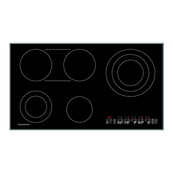
Summary of Contents for Kuppersbusch EKE 8752.0
- Page 1 Touch-Control electronics with slider function EKE 8752.0 EKE 8752.0 EKEF 8752.0 EKE 8852.0 EKEF 8852.0 (TE) EKE 9852.0 (TE) EKE 6542.0...
- Page 2 Service Manual: H1-68-02 Responsible: D. Rutz KÜPPERSBUSCH HAUSGERÄTE AG Email: dieter.rutz@kueppersbusch.de Tel.: (0209) 401-733 Kundendienst Fax: (0209) 401-743 Postfach 100 132 Date: 30.4.08 45801 Gelsenkirchen...
-
Page 3: Table Of Contents
H1-68-02 Contents Safety ..........................4 General Information ....................... 5 Overview EKE 80 cm ..................... 6 Overview EKE 90 cm ..................... 7 Overview EKE 6542.0 ..................... 8 Touch-Control operations ..................... 9 Putting the hob into operation ................9 Turning the hob on ....................9 Power settings....................... -
Page 4: Safety
H1-68-02 Safety Danger! Repairs must be carried out by a qualified expert! Incorrect repairs can be extremely dangerous for the user. It is essential that you observe the following instructions in order to prevent electric shocks: • The casing and the frame may be live in the event of faults! •... -
Page 5: General Information
H1-68-02 General Information Changing the specification or attempts to modify the product are dangerous. For your own safety spare parts should be installed by an authorised, qualified specialist. The manufacturer accepts no liability for damage which occurs as a result of improper installation or failure to observe currently-valid regulations for this type of application. -
Page 6: Overview Eke 80 Cm
H1-68-02 Overview EKE 80 cm 13 15 21 20 22 19 15. Multi-circuit control lamp 1. Cooking zone 21cm / 17.5cm / 12cm / 2.3 kW 16. STOP/GO key 2. Cooking zone 18cm / 12cm / 1.7 kW 17. Key sensor (lock key) 3. -
Page 7: Overview Eke 90 Cm
H1-68-02 Overview EKE 90 cm 19. STOP/GO key 1. Cooking zone 18cm / 12cm / 1.7 kW 20. Key sensor (lock key) 2. Cooking zone 18cm / 1.8 kW 21. Control lamp lock 7. Glass ceramic hob 22. Automatic boost function key 8. -
Page 8: Overview Eke 6542.0
H1-68-02 Overview EKE 6542.0 11. Plus-Minus key 1. Cooking zone 21cm / 17.5cm / 12cm / 2.3 kW 12. Power setting display 2. Cooking zone 14.5cm / 1,2 kW 13. Circuit activation key 3. Cooking zone 14cm / 14x24 cm / 2.3 kW 14. -
Page 9: Touch-Control Operations
H1-68-02 Touch-Control operations Putting the hob into operation The displays are switched on for approx. 1 second when the power supply is switched on. The software versions of the processors will then be shown for approx. 3 seconds. A "P" will appear in the timer display. The software version of CPU2 will appear in the 2 power setting displays. -
Page 10: Selecting The Power Setting By Pressing The Key
H1-68-02 Selecting the power setting by pressing the key The ceramic glass hob is operated with touch control sensor keys. The sensor keys are operated as follows: lightly touch a symbol on the surface of the ceramic glass plate. A buzzer will indicate when the controls have been operated correctly. -
Page 11: Switching Off
H1-68-02 The faster the movement, the faster the change in the display. touch move Switching off If the slider is kept pressed in the minus zone for another 2 seconds at power level 1, the cooking zone will be switched off and a "0" will be shown in the display for 2 seconds. The cooking zone will only be switched on again when it has been recognised that the slider is not being pressed. -
Page 12: Multiple-Circuit Cooking Zones
H1-68-02 Multiple-circuit cooking zones For cooking zones with several heating circuits, the additional heating circuits can be activated by pressing the circuit activation key. The control lamp (circuit activation) in the respective power level display blinks or lights up. Second heating circuit activated: the control lamp blinks. -
Page 13: Childproof Lock
H1-68-02 6.11 Childproof lock The childproof lock is activated by pressing the key sensor for approx. 2 seconds after the SAFE function has been activated. An activated childproof lock function is displayed with the LED on the key sensor. The plus zone of the slider and the circuit activation keys as well as the timer slider and the ON key are deactivated. -
Page 14: Residual Heat Display
H1-68-02 6.13 Residual heat display There is a metre for each cooking zone. If the heater is switched on, a certain figure will be added, depending on the count shown on the metre: The metre is limited to 25440. If the heater is switched off, a certain figure will be deducted, depending on the count shown on the metre. -
Page 15: Stop Function
H1-68-02 6.14.1 Changing the timer setting The timer setting can be changed at any time when the timer is in operation. The change is made with the following sensor functions: Pressing the plus or the minus key will raise or lower the time in minutes. The time will be changed if you leave your finger on a sensor. -
Page 16: The Menu
H1-68-02 The menu Generally the slider will currently only operate for individual menu steps. This means that after each change the key will need to be pressed again to make another setting. When the menu key is pressed the time display will show F1. Pressing the plus or minus zones of the timer slider will enable switching between F1, F2 and F4 (F3 is skipped if no of no pan recognition function has been installed). -
Page 17: Special Features Of The Eke 6542.0
H1-68-02 Special features of the EKE 6542.0 The EKE 6542.0 with four cooking zones has no menu key, so that all the functions are occupied by other keys or combinations of keys. The menu will be activated when the timer and the automatic boost function are pressed simultaneously for five seconds. -
Page 18: Pan Recognition Sensor (Only Eke 8852 And Ekef 8852)
H1-68-02 Pan recognition sensor (only EKE 8852 and EKEF 8852) The pan recognition sensor is automatically activated as soon as the expansion board "for pan recognition" has been inserted. This can be recognised on the touch control as soon as the menu is opened. -
Page 19: Sensor Locks
H1-68-02 The pan recognition sensor can be calibrated from two operating modes. After the hob has been switched on, when "OFF" is shown in the display, the pan recognition sensor can be calibrated by pressing the key sensor (lock) for a long time. The display will then show CALt for 2 seconds. -
Page 20: Excessive Temperature Cutoff
H1-68-02 Excessive temperature cutoff The hob will be switched off if the temperature rises excessively (> 105°C) , a buzzer will sound for one second and the timer display will show E3. As soon as the temperature drops to < 103°C, the E3 error code will go off and the hob can be switched on again. -
Page 21: Wiring Diagrams
Wiring diagrams 13.1 EKE 6452 / EKE 8452... -
Page 22: Eke 6452 / Eke 8452 Clamp Connection Schedule
13.2 EKE 6452 / EKE 8452 clamp connection schedule... -
Page 23: Eke 8752 / Eke 8852
13.3 EKE 8752 / EKE 8852... -
Page 24: Eke 6452 / Eke 8452 Clamp Connection Schedule
13.4 EKE 6452 / EKE 8452 clamp connection schedule... -
Page 25: Eke 8752 / Eke 8852
13.5 EKE 8752 / EKE 8852... -
Page 26: Eke 9852
13.6 EKE 9852... -
Page 27: Eke 9852 Clamp Connection Schedule
13.7 EKE 9852 clamp connection schedule... -
Page 28: Mains Cables
H1-68-02 Legend Deutsch Englisch H-Links/schwarz H-left/black schwarz black weiss white H-Rechts/grün H-right/green gelb yellow blau blue grau grey braun brown V-Links/weiss V-left/white orange orange Spannung 230V 50-60Hz voltage 230V 50-60 Hz Gehäuse housing Anschlussplan wiring diagram Betriebsspannung operating voltage violett violet H-Mitte/rot H-centre/red... -
Page 29: Allocation For Operation To Relay Outputs
Allocation for operation to relay outputs The control elements are numbered from right to left, i.e. control area 1 = far left, control area 2 = second from left, … TYPE Cooking zone 1 Cooking zone 2 Cooking zone 3 Cooking zone 4 Cooking zone 5 1: 6542...
Need help?
Do you have a question about the EKE 8752.0 and is the answer not in the manual?
Questions and answers