Table of Contents
Advertisement
Quick Links
AUTOPILOT
P I LOTSTAR D
Typ AP02- -S01
1 Description
2 Operation
3 Care, Maintenance and Shipboard Repair
4 Installation, Putting into Operation
3060.DOC012 Edition: May 09, 2012
Raytheon Anschütz GmbH
Postfach 1166
D - - 24100 Kiel
Germany
Tel +49- -4 31- -30 19- -0
Fax +49- -4 31- -30 19- -501
Email Service@raykiel.com
www.raytheon- -anschuetz.de
Advertisement
Table of Contents

Subscribe to Our Youtube Channel
Summary of Contents for Raytheon Anschütz Pilotstar D
- Page 1 Raytheon Anschütz GmbH Postfach 1166 D - - 24100 Kiel Germany Tel +49- -4 31- -30 19- -0 Fax +49- -4 31- -30 19- -501 Email Service@raykiel.com www.raytheon- -anschuetz.de AUTOPILOT P I LOTSTAR D Typ AP02- -S01 1 Description 2 Operation 3 Care, Maintenance and Shipboard Repair 4 Installation, Putting into Operation 3060.DOC012 Edition: May 09, 2012...
- Page 2 Weitergabe sowie Vervielfältigung dieser Unterlage, Verwertung und Copying of this document, and giving it to others and the use or Mitteilung ihres Inhaltes nicht gestattet, soweit nicht ausdrücklich communication of the contents thereof, are forbidden without express zugestanden. Zuwiderhandlungen verpflichten zu Schadenersatz. authority.
- Page 3 Set heading differing by more than 180 from the ship’s current actual heading are not executed over the shorter heading by the PILOTSTAR D. The set heading change is carried out to corresponding with default set heading > 180. Note "...
- Page 4 P I L O T S T A R D SAFETY REGULATION Note " Autopilot operation at high speeds. (HSC High Speed Craft, according to IMO guidelines from 30kn to 70kn) On pages HSC--1, HSC--2 and HSC--3 the behaviour rules for the following situations are documented: 1.
-
Page 9: Table Of Contents
PILOTSTAR D Autopilot CONTENTS page Description ............ - Page 10 PILOTSTAR D CONTENTS page Operating Instructions ..........
- Page 11 PILOTSTAR D Autopilot CONTENTS page Change--over of between Main and Secondary Operator Units / Tiller ..2--44 2.5.1 Change--over between a Main Operator Unit and a Secondary Operator Unit 2--44 2.5.2 Change--over to Tiller Control (FU / NFU) .
- Page 12 ..........4--7 Initial Power Application and Testing of Pilotstar D, dock side test and alignment 4--9 Installation of the Feedback Unit (Type 101--529) .
- Page 13 PILOTSTAR D Autopilot List of Abbreviations: -- NMEA telegram header “APA” -- NMEA telegram header “APB” CNT.RUD -- counter rudder HEADINGMON -- heading monitoring (Magnet, Gyro) CRS.TYPE -- heading type -- central processor unit CONFIG. on -- configuration mode on CONFIG.
- Page 14 PILOTSTAR D MAG TYPE -- magnetic sensor type MAGNET FAIL -- magnetic failure NAV TYPE -- navigation data type NAVDATA FAIL -- navigation data failure -- non--follow--up NMEA -- National Marine Electronics Association OFF TRK -- off--track, OFF CRS -- off--heading...
- Page 15 PILOTSTAR D Autopilot TRIM YAW -- 2nd parameter for yawing (TRIM MODE) TRIM RUD -- 2nd parameter for rudder (TRIM MODE) TRIM CNT -- 2nd parameter for counter rudder (TRIM MODE) TRACK LIM -- track limit -- waypoint WOP--circle -- wheel over point circle...
- Page 16 PILOTSTAR D Attention Change of “Preselected heading” A change of preselected heading can be done by using the rotary knob or the Port/ STBD arrow keys. In both modes the ship follows the respective heading adjustment within a range of 0 to 359,9.
-
Page 17: Description
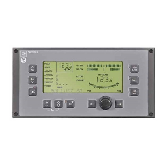
PILOTSTAR D Autopilot Description General The PILOTSTAR D is a comfortable digital autopilot system ensuring safe and simple handling. The PILOTSTAR D offers the following steering modes: -- Heading control acc. to a manually adjusted set heading preselection -- Heading control with rudder trim function (work mode) - Page 18 PILOTSTAR D The monitoring field (see also Annex --1) indicates -- the current heading (actual heading) as a digital display. Below the heading dis-- play, the selected heading sensor type will be faded in. GYRO for gyro compass for magnetic compass or fluxgate compass.
- Page 19 The autopilot here receives its set heading preselections via an external navigation system. The PILOTSTAR D track controller now cannot be activated; change--over to the operating mode TRACK is not possible. Manual set heading preselection via the PORT/STBD keys or via the rotary knob is not possible now.
- Page 20 PILOTSTAR D Keys in the operating field Auto changes over to the operating mode of heading control (LED alight); On/Off changes over to the operating mode of track control (LED alight) Track changes over to the operating mode of manual control (LED alight;...
-
Page 21: The Connection Unit
PILOTSTAR D Autopilot Rudder angle indicator The centric segment describes the rudder order. Passing over from one seg- PORT STBD ment to another corresponds to a rudder movement of 2. The rudder limitation Rudder Rudder describes the permissible limit range for the rudder movement. -
Page 22: General Information On The Autopilot Configuration
PILOTSTAR D General Information on the Autopilot Configuration Exact heading control or track control depends on the various basic adjustments of the autopilot (for detailed information see Chapter 2.3, Chapter 2.4 and Chapter 4.13). A difference is made of between the ship--specific and the operational adjustment of pa- rameters. -
Page 23: Principle Of Operation
PILOTSTAR D Autopilot Principle of Operation The autopilot is used for the automatic heading or track control. A microprocessor--con- trolled control circuit -- taking into account the ship--specific and operation--conditioned adjustment -- takes over the ship’s steering control (see Fig. 1--2). -
Page 24: Heading Control With Set--Heading Preselection
PILOTSTAR D 1.3.1 Heading Control with Set- -heading Preselection The set heading value is to be varied by re--adjusting the rotary knob or the arrow keys. The rudder angle indicator will be deflected correspondingly and indicates the rudder order. The ship turns with the desired rate--of--turn pre--setting (ROT / MIN) and with taking into account the current speed (if LOG SENSOR available, otherwise manual preselection, SPEED) into the new set heading (see Fig. -
Page 25: Heading Control With Automatic Set Heading Preadjustment
With this, the set heading is determined by the navigation system and transmitted to the PILOTSTAR D via a serial interface. The PILOTSTAR D performs the heading control. The status field EXT.CRS is faded into the LCD display. During this operating mode, the manual set--heading input (rotary knob or arrow keys) and change--over to the operating mode TRACK are not possible. -
Page 26: Track Control
If XTE telegram transmission is used, the operation will be different. First of all, the new track course is to be read off the navigation receiver and to be adjusted on the PILOTSTAR D via the rotary knob. The following example shows a route consisting of 3 waypoints and 2 track sections. -
Page 27: Heading And Sensor Monitoring
PILOTSTAR D Autopilot Heading and Sensor Monitoring The autopilot is equipped with an extensive monitoring electronics. In case of trouble, audible and visual alarm will be released. The availability of the heading sensors or the function of the steering gear, etc., is contin- uously monitored. -
Page 28: Function Of The Trim Mode (Trm)
PILOTSTAR D Function of the TRIM MODE (TRM) The TRIM Mode is a so called “Working Mode” and could be essential to ships with low speed, as there could be trawlers, towboats (tugs) or other work boats. The Trim Mode is nearest a heading control function with specific operating features. - Page 29 PILOTSTAR D Autopilot Trawlers with an asymmetrical load caused by a trawl net and manoeuvre opera- tion Application of the parameter TRM--rudder (Trim rudder). The parameters are adjusted in that manner that the heading control will steer the ship with a small rudder amplification and the rudder can be trimmed additional manually (de- pending on the specific requirement).
-
Page 30: Summarization
PILOTSTAR D 1.5.2 Summarization Switching--over from heading control to TRIM MODE -- Trim parameters are activated. -- Rudder limit is turned--off -- Heading control (with all features) is active. TRM--rudder is applied -- Adjusting the trim rudder in 1 steps by the arrow keys. -
Page 31: System Extension
PILOTSTAR D Autopilot System Extension The connection unit of the autopilot permits a simple and quick system extension; further system PCBs are not required (see Fig. 1--5). 1.6.1 Main and Secondary Operator Units In addition to the main operator unit, 2 further operator units of the same type can be connected to the connection unit of the autopilot as secondary steering stations. -
Page 32: Central Alarm System
The alarm muting is solved bidirectional, that means an alarm which is local cancelled will be muted also on the Central Alarm Panel and vice versa. The Pilotstar D must be configured to ’ RELAY ALARMS’ according to section 4.7, sub- item 10. -
Page 33: Connection Of A Steering Repeater
PILOTSTAR D Autopilot 1.6.6 Connection of a Steering Repeater As an alternative to the digital navigation data indicator, this serial output can also be used for connecting an Raytheon Anschütz steering repeater with specific Software (RS422 output) ( Configuration A--REP). - Page 34 PILOTSTAR D -- Interfaces for possible sensors -- Gyro compass with transmission system: Raytheon Anschütz course bus system Raytheon Anschütz step system 1/6 Step--system -- Magnetic compass with transmission system: Raytheon Anschütz scanning sonde Fluxgate sonde with sine/cosine DC voltage...
-
Page 35: Interface Description Acc. To Nmea 0183, Version 2.1 October 1997
(set heading, actual heading, speed) Serial output RS422 for Raytheon Anschütz steering repeater ( with spec. Software) Feedback unit -- Supply via PILOTSTAR D: 15V DC -- Type of enclosure: IP 56 -- Ambient temperature: --25 to +55 1.7.2 Interface Description acc. - Page 36 PILOTSTAR D NMEA 0183 Format APB APB Autopilot Sentence ”B” Waypoint,Magnetic or True Mode Indicator Bearing,Present position to destination,Magnetic or True Destination waypoint ID Bearing origin to destination,M/T Status:A= perpendicular passed at waypoint Status:A= arrival circle entered XTE units,nautical miles...
- Page 37 PILOTSTAR D Autopilot NMEA 0183 Format VTG VTG Course Over Ground and Ground Speed SOG, km/hr Speed, knots Course, degrees Magnetic Course, degrees True Talker NMEA 0183 Format VHW VHW Water Speed and Heading Speed, km/hr...
-
Page 38: Output Interface
PILOTSTAR D (E03...) Heading, degrees Magnetic Talker NMEA 0183 Format HDT HDT Heading True (9600 Baut Rate, cycle 100ms) Heading, degrees True Talker 1.7.2.2 Output Interfaces NMEA 0183 Format HEHDT HEHDT Gyro--Compass sentence Checksum Degrees true... - Page 39 PILOTSTAR D Autopilot Property NMEA 0183 Format PADRT PADRT Rate of turn limit (adjusted on autopilot operator panel) $PADRT,xxx.x<(CR)><(LF)> Heading (uncorrected) String format for heading uncorrected Talker identifier (property Raytheon Anschütz) Start of sentence Property NMEA 0183 Format IICTS IICTS ...
- Page 40 PILOTSTAR D Property NMEA 0183 Format PASHE PASHE If heading is valid $PASHE,A<(CR)><(LF)> Heading information is valid String format for heading status Talker identifier (property Raytheon Anschütz) Start of sentence Property NMEA 0183 Format PASHE PASHE If heading is not valid $PASHE,V<(CR)><(LF)>...
- Page 41 (RS232) Ship’s mains 10..36V DC Analog repeater (RS422) Steering mode selector Tiller FU/NFU (option) Feedback unit External rudder position indicator Secondary operator unit Bi--drectional alarm outputs Fig. 1- -5: The PILOTSTAR D System Concept 1--25 3060.DOC012 Edition: March 13, 2009...
- Page 42 PILOTSTAR D Intentionally left blank 1--26 Edition: March 13, 2009 3060.DOC012...
-
Page 43: Operating Instructions
PILOTSTAR D Autopilot Operating Instructions SAFETY NOTES ATTENTION In opened devices or desks, voltages representing a risk of electric shock are applied. - - SAFETY INSTRUCTION - - As a matter of principle, the system is to be made dead when installation work is performed on the equipment as well as during disassembly/assembly of components or during alteration of the circuitry. -
Page 44: Checks To Be Made Before Any Putting Into Operation
PILOTSTAR D 2.1.2 Checks to be made before any Putting into Operation In order to ensure correct functioning of the autopilot, faultless operation of the following systems and devices is required: Power supply -- for the equipment concerned -- 10 ... 36V DC for the autopilot ... -
Page 45: Change--Over To Another Heading Sensor
PILOTSTAR D Autopilot 2.1.5 Change- -over to another Heading Sensor Change--over to another heading sensor may result in a considerable SET HEADING deviation. In order to avoid unintended reactions of the ship on changing over, the set heading is equated with the heading. -
Page 46: General Operation And Pre--Conditions
PILOTSTAR D General Operation and Pre- -conditions The following chapters describe each key function, the corresponding indication and the effects on steering control. For actively testing certain operator actions on the operator unit, a completely installed autopilot is required here. -
Page 47: Explanation Of Symbols Used
PILOTSTAR D Autopilot 2.2.1 Explanation of Symbols Used Key actuation LED flashing LED out LED on Audible signal on Audible signal off Status panel flashing CONFIG Index for display explanation 2--5 3060.DOC012 Edition: March 13, 2009... -
Page 48: Prerequisite For Switching On The Operating Mode Track Control
PILOTSTAR D 2.2.2 Prerequisite for Switching on the Operating Mode TRACK CONTROL This operating mode presupposes certain operator actions, i.e. track planning, on the navigation receiver. See manufacturer’s handbook of the navigation receiver in question. Prior to switching to the operating mode of track control, the following recommendations... -
Page 49: Putting Into Operation
Autopilot 2.2.3 Putting into Operation With connecting the ship’s mains supply (ship’s mains fuse ON), the PILOTSTAR D is ready for operation. The following survey shows the possible operating conditions / operating modes. Connecting the ship’s mains voltage ... -
Page 50: The Status Indication Standby Is Visible
2. The steering mode selector has been set to position AUTO. The main operator unit is active -- the AUTO LED is on. If the tiller steering (Pilotstar D) is selected, the operation panel changes over to STAND BY Mode ... -
Page 51: Switching On The Autopilot (Standard Equipment)
PILOTSTAR D Autopilot 2.2.5 Switching on the Autopilot (Standard Equipment) The autopilot is activated via the steering mode selector, switch position AUTO. HAND AUTO The operating mode HEADING CONTROL is now active (see Chapter 2.2.6). Change--over to another operating mode is now possible. -
Page 52: The Operating Mode Heading Control
PILOTSTAR D 2.2.6 The Operating Mode HEADING CONTROL By actuating the key, the heading control is activated. The instantaneous HEADING is accepted as SET HEADING preselection. The ship is held on the instantaneous heading. The LED panel of the key is alight (GREEN). -
Page 53: Set Heading Change
PILOTSTAR D Autopilot 2.2.6.1 SET HEADING Change ATTENTION The heading change manoeuvre is initiated immedi- ately. The ship starts turning with the preset rate of turn (RATE OF TURN) into the preset SET HEADING input. During a heading change manoeuvre, the parameter value for rate of turn (ROT /MIN) must not be varied ! - Page 54 PILOTSTAR D In case of a SET HEADING CHANGE, the display indication is as follows: Limit adjustment for the With the new SET HEADING presetting, the limit adjustment OFF HEADING has been exceeded; the corresponding range is flashing monitoring limits...
-
Page 55: Automated Set Heading Change (Fix Turn)
PILOTSTAR D Autopilot 2.2.6.2 Automated SET HEADING Change (FIX TURN) The automated SET HEADING change is only possible when in the Heading Control mode of operation. The heading change maneuver is initiated immedi- ATTENTION ately. The ship begins to turn to the newly set SET HEAD- ING from the previously set R.o.T. - Page 56 PILOTSTAR D Indications Remark/Notes Execute SET HEADING Presetting (e.g. 90 STBD) © The acoustic and optical signals cease. PARAM Release the key. VARI. OFF CRS GYRO LIMITS YAWING SET COURSE In this example, the SET HEADING RUDDER STANDBY presetting is increased by 90.
-
Page 57: Operating Mode Heading Control With A Preceding Set Heading Transmitter, Remote Operation
Heading differences will be sensed by the navigation system and passed on to PILOTSTAR D for heading correction. Change--over to another PILOTSTAR D operating mode or change--over to a tiller is not possible now. Re- -adjustment of the set heading preselection via PORT/STBD keys or via rotary knob is not possible now. - Page 58 An external set heading preselection initiates the heading change manoeuvre as a function of the rate of turn preset on the PILOTSTAR D. The direction (PORT or STBD) is realistically indicated by the movement of the bar graph segment in 2 steps.
-
Page 59: The Operating Mode Track Control
PILOTSTAR D Autopilot 2.2.8 The Operating Mode TRACK CONTROL Do not use TRACK CONTROL under high speed condition >25kts. Track Control has no system approval according IEC62065 (ECDIS/Autopilot) 2.2.8.1 Approaching a Track Before changing over to the operating mode of track control, the track to be sailed through must roughly be reached via manual control or via heading control (Step 1) (see Chapter 2.2.6). - Page 60 PILOTSTAR D For taking over the track course data, the symbol key must be actuated for acknowledging. The LED panel of the key becomes dark; the system message in the text line goes out; the audible alarm ceases. The SET COURSE indication now shows the track course and will not change unless a new track is selected.
- Page 61 PILOTSTAR D Autopilot After acknowledgement, the text line is faded out; simultaneously, the NEW TRACK course appears in the SET COURSE indication. If -- after change--over to the operating mode of track control -- the ship is still outside the pre--defined monitoring limits (TRACK MAX and COURSE MON), these parts of the bar graph indication will be flashing.
-
Page 62: Track Change
’123’ track course transmission takes place . crosstrack distance [m] In this case, the track course is to be read off the position receiver and to be adjusted on the PILOTSTAR D manually via the rotary knob. 2--20 3060.DOC012... -
Page 63: The Operating Mode Manual Control (Dodge Function)
PILOTSTAR D Autopilot 2.2.9 The Operating Mode MANUAL CONTROL (DODGE Function) On actuating this double--function key for the first time, the autopilot system changes over to manual control as a matter of principle. Trim The operating modes of HEADING CONTROL or TRACK CONTROL are no longer active now. -
Page 64: The Operating Mode Heading Control With Trim Function (Work Mode)
PILOTSTAR D 2.2.10 The Operating Mode HEADING CONTROL with TRIM FUNCTION (Work Mode) The trim mode should be used when the vessel is operating at reduced speed, such as towing or fishing, due to the elimination of automatic rudder limits. It should never be used in a case where large rudder movements would cause the vessel to react violently or become unstable. - Page 65 PILOTSTAR D Autopilot ATTENTION Switching back to another operating mode may bring about an unintended reaction of the ship! For this reason, the manual rudder presetting should be reset to 0 step by step. Only then, change--over to the intended operating mode is to be made.
-
Page 66: Dimming Of Key And Lcd Illumination
PILOTSTAR D 2.2.11 Dimming of Key and LCD Illumination On actuating one of the keys, the key and LCD display illumination can be adjusted by steps. The main and secondary operator units are always dimmed together. The dimming function is only active when there is no text display in the text Test line. -
Page 67: Varying The Operational Parameter Values
PILOTSTAR D Autopilot Varying the Operational Parameter Values The operational parameters can effectively be varied in any operating mode. If the con- troller basic adjustment (ship--specific parameters) has been optimized for the ship, of- ten there will be required only weather--conditioned adaptations such as e.g. YAWING (see survey in the Annex -- 2 and Chapter 4.13). - Page 68 PILOTSTAR D Indications Remark/Notes ¡ Calling up the parameter sequence The last effective parameter value PARAM YAWING 1 appears in the text line. OFF TRK VARI. OFF CRS GYRO LIMITS YAWING SET COURSE RUDDER STANDBY CNTRUD 10 20 30 SPEED...
-
Page 69: Optimum Adjustment By Test Runs -- Operating Mode Heading Control
PILOTSTAR D Autopilot 2.3.1 Optimum Adjustment by Test Runs - - Operating Mode HEADING CONTROL - - The optimum adjustment can be ascertained by several heading changes of e.g. 10. HAND AUTO -- Set the steering mode selector to position AUTO: The operating mode HEADING CONTROL is active. -
Page 70: Recommended Parameter Values For Various Weather Conditions
PILOTSTAR D 2.3.1.1 Recommended Parameter Values for Various Weather Conditions Parameter values for calm sea YAWING 1 -- 2 RUDDER 2 -- 5 Note: CNT.RUD. 2 -- 5 A high value for YAWING SPEED current results in small rudder angles RUD.LIMIT... - Page 71 PILOTSTAR D Autopilot Parameter TRIM Mode TRIM YAW as required for special task TRIM RUD as required for special task TRIM CNT. as required for special task SPEED current RUD.LIMIT ROT/MIN as required OFF HEADING as required NOTE Generally, attention is to be paid to the fact that the RUD.LIMIT value and the ROT value show an adequate...
-
Page 72: Adjusting The Monitoring Limit For Off Track (Off Trk)
PILOTSTAR D 2.3.2 Adjusting the Monitoring Limit for OFF TRACK (OFF TRK) This monitoring limit requires the operating mode TRACK. The monitoring limit describes the left or right distance to the track run though. Track deviations within the TRACK LIMIT are permissible; if the central dynamic bar graph segment meets with a monitoring limit, an OFF TRACK warning message will be released (see Chapter 2.6.1.1). - Page 73 PILOTSTAR D Autopilot Indications Remark/Notes £ Fading out the text line On actuating the key, the text line is faded out. PARAM OFF TRK VARI. OFF CRS GYRO LIMITS YAWING SET COURSE EXT.CRS RUDDER STANDBY CNTRUD 10 20 30 SPEED...
-
Page 74: Adjusting The Monitoring Limit For Off Heading (Off Crs)
PILOTSTAR D 2.3.3 Adjusting the Monitoring Limit for OFF HEADING (OFF CRS) This monitoring limit requires the operating mode AUTO (heading control) or the opera- ting mode TRACK. The adjusted limit value is the same for the two operating modes, but it describes different indications. - Page 75 PILOTSTAR D Autopilot Indications Remark/Notes © Calling up the parameter value OFF HEADING ..The last effective parameter value OFF HEADING 15 appears in the PARAM OFF TRK text line. VARI. OFF CRS GYRO LIMITS YAWING SET COURSE EXT.CRS RUDDER...
-
Page 76: Adjusting The Rudder Limitation Rudder Limit (Rud.limit)
PILOTSTAR D 2.3.4 Adjusting the Rudder Limitation RUDDER LIMIT (RUD.LIMIT) The rudder limitation is effective in the operating modes of TRACK and AUTO and can be adjusted correspondingly. In the operating modes of MANUAL STEERING (dodge function) and HEADING CON- TROL with TRIM FUNCTION (work mode), the rudder limitation is cancelled. -
Page 77: Optimizing The Control Characteristics Of The Track Controller, Track
PILOTSTAR D Autopilot 2.3.5 Optimizing the Control Characteristics of the Track Controller, TRACK < > The parameter adjustment of the track controller is preset as a standard for normal wind or current conditions. If, however, a heavy drift occurs for instance, a considerable track error may be the result. - Page 78 PILOTSTAR D Indications Remark/Notes £ Fading out the text line By actuating the key, the text line will PARAM be faded out OFF TRK VARI. OFF CRS GYRO LIMITS YAWING SET COURSE EXT.CRS RUDDER STANDBY CNTRUD 10 20 30 SPEED...
-
Page 79: Synchronization Of The Autopilot For A Gyro Compass With Step Transmission
In case of a gyro compass system whose type of signal transmission corresponds to an ACO Step STANDARD 14 or 1/6 Step signal (see Annex -- 3), the PILOTSTAR D must be synchronized new after any putting into operation or after a short--time voltage failure. - Page 80 PILOTSTAR D Indications Remark/Notes ¢ Calling up the parameter value SYNCHRON On actuating the key several times, PARAM the parameter SYNCHRON..ad- OFF TRK VARI. justs itself in the text line. OFF CRS GYRO LIMITS SET COURSE YAWING EXT.CRS RUDDER...
-
Page 81: Ship--Specific Parameters (Config. On)
PILOTSTAR D Autopilot Ship- -specific Parameters (CONFIG. on) As a matter of principle, the autopilot is delivered with preset parameter values (see An- nex --1, column DEFAULT). Adjustment of the ship- specific parameters is required only in conjunction with first installation or in case of system extension (see Chapter 4.10 and 4.13). -
Page 82: Adjusting The Ship--Specific Parameters
PILOTSTAR D 2.4.1 Adjusting the Ship- -specific Parameters As an example, a new XTE TRIM parameter value is to be adjusted here, in the mean- ing of: The integration time of cross track error (fast and slow). Short information on the XTE TRIM parameter and on the situation when a new value should be adjusted. - Page 83 PILOTSTAR D Autopilot Indication Remark/Notes ¡ Operating mode TRACK is active, the ship oscillates, e.g. about the track course The actual heading continuously PARAM changes by e.g. 15. The default OFF TRK VARI. value of the XTE parameter must be...
- Page 84 PILOTSTAR D Indications Remark/Notes ¤ Adjusting the parameter value 100 The desired value can be adjusted PARAM by repeated actuation (the value OFF TRK VARI. changes by jumps of tens). OFF CRS GYRO LIMITS YAWING SET COURSE EXT.CRS RUDDER STANDBY...
- Page 85 PILOTSTAR D Autopilot Indications Remark/Notes Call up cross track error ¨ The current distance from the track PARAM is indicated for approx. 3s. OFF TRK Track VARI. The optimum XTE TRIM parameter OFF CRS GYRO LIMITS value is to be ascertained by observ-...
-
Page 86: Change--Over Of Between Main And Secondary Operator Units / Tiller
PILOTSTAR D Change- -over of between Main and Secondary Operator Units / Tiller Change--over of between the main and secondary operator units or the tillers is always performed via the intended steering station. 2.5.1 Change- -over between a Main Operator Unit and a Secondary Operator Unit... -
Page 87: Change--Over To Tiller Control (Fu / Nfu)
-- The rudder angle indicator indicates the current rudder position. © Switching back to the PILOTSTAR D With actuating the key on the tiller, Auto the following state adjusts itself: PARAM Auto OFF TRK VARI. -
Page 88: Signification Of The System Messages In The Autopilot
PILOTSTAR D Signification of the System Messages in the Autopilot As a matter of principle, system messages are indicated via the text line as plain text in- formation. Dependent on the significance of the message, a text in the text line is over- written by the system message. -
Page 89: Signification Of Possible Warnings In The Text Line
OFF HEADING The monitoring lim- see Chap. 2.3 its have been se- RUD.LIM lected too narrow; extend, if required. PILOTSTAR D or Change over to op- Trim steering output is erating mode see Chap. 2.2.9 defective. ”Manual Control”. -
Page 90: Signification Of Possible Notes Within The Text Line
PILOTSTAR D Warnings Signification Possible Measures on the Opera- Measures tor Unit/Periphery HEADING MON The heading from Check the mag- the magnetic com- netic heading pass is outside the correction. monitoring limits. Check the opera- tional parameters: adapt, if required. -
Page 91: Disturbed Operation
PILOTSTAR D Autopilot 2.6.2 Disturbed Operation ”Disturbed Operation” means that under these conditions a unique operating state of the autopilot is no longer possible. Any fault message is indicated as plain text via the text line; simultaneously, audible alarm is given. - Page 92 PILOTSTAR D Intentionally left blank 2--50 3060.DOC012 Edition: March 13, 2009...
-
Page 95: Safety Notes
PILOTSTAR D Autopilot Care, Maintenance and Shipboard Repair SAFETY NOTES ATTENTION Observe Precautions for Handling Electrostatic Sensitive Devices CAUTION Handling of Electrostatic- -sensitive Semiconductor Devices Certain semiconductor devices used in the equipment are liable to damage due to static voltage. Observe the following precautions when handling these parts or sub--units of the system components which, because of the now open inputs of the semiconductor devices, are endangered by static charge. -
Page 96: Ship's Safety
PILOTSTAR D 3.1.1 Ship’s Safety According to the GERMAN LLOYD and to other regulations, the autopilot has been clas- sified as a SECONDARY STEERING SYSTEM, i.e. without redundant installation nor internal redundancy. A MAIN STEERING SYSTEM, however, for example manual con- trol, must be installed twice and without reactive effects. -
Page 97: Care And Maintenance
PILOTSTAR D Autopilot Care and Maintenance 3.2.1 Care The PILOTSTAR D system requires no care. 3.2.2 Maintenance The PILOTSTAR D system is maintenance--free. 3--3 3060.DOC012 Edition: March 13, 2009... -
Page 98: Shipboard Repair
PILOTSTAR D Shipboard Repair See Fig. 3--2 3.3.1 Exchanging the Fuse in the Connection Unit The fuse (T 2A) is located on the junction PCB. For exchanging the fuse, the hood of the connection unit is to be removed (see Junction PCB 102 D 863 HP010). - Page 99 PILOTSTAR D Autopilot The PILOTSTAR D is initialized with the ship--specific parameter values. NOTE For a gyro compass with STEP transmission, the synchronization gets lost in case of a WARM START (see Chapter 2.3.6). The LCD display indication is as follows:...
-
Page 100: Exchanging A Pcb
PILOTSTAR D 3.3.3 Exchanging a PCB Before the PCB is exchanged, the hood and the cover plate are to be removed (see Fig. 3--2). The PCBs are to be removed and to be inserted by means of their PCB drawers. -
Page 101: Led Displays On The Cpu Pcb
PILOTSTAR D Autopilot LED Displays on the CPU PCB The LEDs are located on the front side of the CPU PCB. H2 H3 H4 H5 Service switch B113 Fig. 3- -3: LEDs on the CPU PCB Colour Indica- Cause Measure... -
Page 102: Repair
PILOTSTAR D Repair 3.5.1 Block Diagram of the I/O PCB Supply volt- Power fail (CPU PCB) Monitoring age (ship’s mains) + 5V supply 32VDC 15V supply 12/24VDC + 5V Serial data Selection ON signal for signal unit of steering... -
Page 103: Test Points Of The I/O Pcb
PILOTSTAR D Autopilot 3.5.1.1 Test Points of the I/O PCB Test Points (TP) Signification Remark Test Contacts B20.x and B21.x TP 1 Signal ground (GND, AGND) B21.5 + 15V Electrically isolated voltage Electrically isolated voltage B21.2 supply for analog rudder out-... -
Page 104: Block Diagram Of The Cpu Pcb
PILOTSTAR D 3.5.2 Block Diagram of the CPU PCB I/O- -Interface Electric isolation Inte-- grator Dimmer Aco--/Sperry-- Electric Timer step isolation Rudder (Clock signal for analog rudder ac- Electric tivation) isolation Tiller 1..3 sin / cos Serial data Feedback unit... -
Page 105: Installation, Putting Into Operation
PILOTSTAR D Autopilot Installation, Putting into Operation SAFETY NOTES ATTENTION In opened devices or desks, voltages representing a risk of electric shock are applied. - - SAFETY INSTRUCTION - - As a matter of principle, the system is to be made... -
Page 106: Installation Planning And Instruction
PILOTSTAR D Installation Planning and Instruction 4.3.1 Operator Unit (Dimensional Drawing 102D864.HP005) Requirements to be met by the mounting site: The device has to be readily visible and be placed such as to ensure convenient handling. For the flush mounting, refer to the Dimensional Drawing 102D864.HP005 (recess and drilling scheme). -
Page 107: Cabling Of The Equipment
PILOTSTAR D Autopilot Cabling of the Equipment The cabling of the equipment is ship--specific, refer to the enclosed Connection Diagram AP02 C S01 HP051. The --POWER SUPPLY-- ship’s cable must be passed through the ferrite absorber be- fore wiring is carried out; refer to the following diagram. -
Page 108: Ship--Specific Parameters (Config. On)
PILOTSTAR D Ship- -specific Parameters (CONFIG. on) As a matter of principle, the autopilot is delivered with preset parameter values (see An- nex -- 4, column DEFAULT). As a principle, the adustment of the ship- -specific parameters is only required on the occasion of first installation or in case of system extension. -
Page 109: Adjusting The Ship--Specific Parameters
PILOTSTAR D Autopilot 4.5.1 Adjusting the Ship- -specific Parameters NOTE Prior to adjustment, the autopilot is to be switched into the STANDBY mode. Set the steering mode selector to MANUAL CON- TROL. HAND AUTO Indications Remark/Notes ¡ Calling up the parameter sequence PARAM Actuate the key until CONFIG. - Page 110 PILOTSTAR D Indications Remark/Notes Calling up the next parameter £ PARAM Adjusting of the actual ship’s OFF TRK VARI. GYRO length, see point £ LIMITS YAWING SET COURSE RUDDER STANDBY CNTRUD 10 20 30 CONFIG SPEED S_LENGTH .60m PORT STBD Repeat the operations stated under Point £...
-
Page 111: Cold Start
PILOTSTAR D Autopilot Cold start The cold start is released via the software. In case of a cold start, all operational and ship- -specific parameter values are re- placed by the DEFAULT values. 4.6.1 Releasing the Cold Start NOTE Before starting the adjustment, switch the autopilot to STANDBY mode. - Page 112 10 20 30 CONFIG SPEED INITIALIZED PORT STBD ¦ After the cold start The PILOTSTAR D is now ready for operation. The ship--specfic PARAM OFF TRK and operational parameter values VARI. GYRO LIMITS are set to default and can now be...
-
Page 113: Initial Power Application And Testing Of Pilotstar D, Dock Side Test And Alignment
-- position F1 for 32V supply voltage -- position F2 for 12 to 24V supply voltage. Switch the ship fuse ”ON”. Pilotstar D should now go through its self test and then to ”STANDBY” mode (s. Chapter 2.2.4). If the text line indicates the message ”SYNCHRON”... - Page 114 PILOTSTAR D Heading sensor selection. If the PILOTSTAR D is equipped with a gyro compass input, go to step #9. If the Pilotstar D uses Magnetic Compass only, use the key to scroll to ”COMPASS” and select ”MAGNETIC” using the key.
- Page 115 (DIFF MODE). Hereby, the control loop for the rudder position is closed via the FU amplifier of the PILOTSTAR D. For variation, the actual rudder signal must be fed back via the RUDDER FEEDBACK terminal (refer to AP02 C S01 HP050).
- Page 116 PILOTSTAR D RUD FAIL: Threshold for the alarm which monitors rudder response. The Feedback unit must be installed to enable this function (s. Chapter 4.8). The number selected is the difference between rudder order and rudder angle which will sound the alarm. A setting of ”0”...
- Page 117 If the gyro compass is a Raytheon Anschütz Gyro, verify that the gyro compass heading matches the gyro indication. Note If the Pilotstar D is provided for analog output and An- schütz rudder angle indicators and feedback unit are not used, step #13, #14, #15, #16 and #17 can be bypassed.
- Page 118 PILOTSTAR D 17.3 Press the key. The LED should now illuminate and the rudder will Auto Auto On/Off On/Off move to zero degrees. The ”SET HEADING” display should match the heading indication in the upper left corner. 17.4 Increase the SET HEADING about 10 port (using the heading setting knob).
- Page 119 Note Possible alarms and causes: ”NAVDATA FAIL”: The Pilotstar D is not receiving any data from the navigation receiver. Possible causes include broken or incorrectly connected wiring, reversal of input to Pilotstar D Connection Unit, selection of RS--232 rather than RS--422 at navigation receiver or output port of Navigation receiver not enabled (refer to corresponding GPS description).
- Page 120 PILOTSTAR D If this should not be the case, repeat the test on the PILOTSTAR D as follows: -- Observe the LED H5 on the CPU PCB. If this LED flashes with the on and off action of the jumper, then probably the wrong interface format has been set (see step #9 LOG TYPE).
-
Page 121: Installation Of The Feedback Unit (Type 101--529)
PILOTSTAR D Autopilot Installation of the Feedback Unit (Type 101- -529) NOTE Prior to adjustment, the autopilot is to be switched into the STANDBY mode. Set the steering mode selector to MANUAL CON- TROL. HAND AUTO Measuring instrument: A commercial voltmeter is to be made available as a measuring instrument. -
Page 122: Adjusting The Limit Switches Of The Feedback Unit
PILOTSTAR D Mounting the transmission element: Linkage transmission By loosening the hexagonal screw on the pulley, the pulley position can adequately be corrected. Toothed--belt transmission The toothed belt can directly be applied. Pay attention to the belt tension indicated in the dimensional drawing. - Page 123 PILOTSTAR D Autopilot Hexagonal screw Pulley Fig. 4- -1: Balancing the Feedback Unit, Typ 101--529 4--19 3060.DOC012 Edition: March 13, 2009...
-
Page 124: Electrical Zero Adjustment On The I/O Pcb (Offset) (Refer To Summary Diagram 102 D 863 Hp011)
PILOTSTAR D Electrical Zero Adjustment on the I/O PCB (OFFSET) (refer to summary diagram 102 D 863 HP011) Pre- -conditions: Set rudder to exactly midships position (0) via manual control. Connect the measuring instrument to the following test points (TP): TP 1 ... -
Page 125: Adjustment And Test Of The Electrical Rudder Scaling (Rud Scale)
PILOTSTAR D Autopilot 4.9.1 Adjustment and Test of the Electrical Rudder Scaling (RUD SCALE) Indications Remark/Notes Calling up or checking the parameter RUD SCALE ¡ For calling up the parameter se- quence, see Chapter 4.5.1, Point PARAM OFF TRK VARI. - Page 126 PILOTSTAR D Adjustment by autopilot function: Indications Remark/Notes ¡ Calling up manual operating mode Prior to calling up the manual op- erating mode, the steering mode PARAM OFF TRK VARI. selector has to be set to position Trim GYRO LIMITS AUTO.
-
Page 127: Adjusting/Checking The Rudder Slack (Rud Slack)
PILOTSTAR D Autopilot 4.9.1.1 Adjusting/Checking the Rudder Slack (RUD SLACK) Indications Remark/Notes Calling up the parameter RUD SLACK ¡ For calling up the parameter se- quence, see Chapter 4.5.1, Point PARAM OFF TRK VARI. ¡ GYRO LIMITS YAWING SET COURSE... - Page 128 PILOTSTAR D Indications Remark/Notes Adjusting the rudder in the fore--and--aft line ¤ On actuating both keys, the rud- der shall move into midship posi- tion without considerable over- swings and assume a stable rud- PARAM OFF TRK VARI. der position.
-
Page 129: Adjusting The Magnet Sonde 108--010
> -- 5.9V, then a set of extended spacing pieces must be used. 2) Turn the probe slowly in its holding ring until the actual heading display (PILOTSTAR D) is identical to that of the magnetic compass heading. (In this setting, check the sense of rotation of the phases): -- if the probe is turned in the direction of higher magnetic compass values, then the actual heading display must be correspondingly larger. - Page 130 R140 until a voltage of +5.5V (--5.5V) appears. 2) Turn the probe slowly in its holding ring until the actual heading display (PILOTSTAR D) is identical to that of the magnetic compass heading. (In this setting, check the sense of rotation of the phases): -- if the probe is turned in the direction of higher magnetic compass values, then the actual heading display must be correspondingly larger.
-
Page 131: Adjusting The Flux--Gate Compass Sonde (With Sin/Cos Output)
PILOTSTAR D Autopilot 4.11 Adjusting the Flux- -gate Compass Sonde (with SIN/COS Output) Notes for a flux--gate compass sonde with a serial data transmission: For this compass type, no adjustment is required. The ship--specific parameter MAG TYP (see Chapter 4.5.1 and Annex -- 4) has to be adjusted for the value 2. -
Page 132: Sea Trial Procedure
(make some heading changes). When the vessel mode selection switch is switched from ”HAND” to ”AUTO” (LED lights up), the PILOTSTAR D operates with standard values for Auto On/Off YAWING, RUDDER, CNT.RUD. - Page 133 Make some additional heading maneuvers; turn the vessel into the wind. Observe the heading stability of the vessel. The PILOTSTAR D begins to compensate the drift effect (rudder offset begin). If the rudder offset takes effect too slowly, the parameter must be increased.
- Page 134 PILOTSTAR D Press the key until ”autotrim ...” appears in the line of text. Press the key until optimal control behavior is achieved. Make a heading change of 180 and check the heading behavior. Press the key until ”ex?=1” appears in the line of text.
- Page 135 PILOTSTAR D Autopilot Storing the optimized parameters: Press the key until ”STORE? sel (Y/N)” appears in the text line. The display switches to ”STORE (Y) SET” by pressing the key once. The setting is stored by pressing the key, ”Data stored”.
- Page 136 PILOTSTAR D The setting of parameter is now completed. It is advisable to enter all ship--specific parameter values in the tables of the Appendices -- 2 and -- 3 in writing. In case of a possible defect, for example of the CPU PCB, the parameter values can be updated quickly after changing the PCB.
-
Page 137: A Guide To When Which Parameters Must Be Set
YAWING HEADING CONTROL or TRACK The YAWING setting defines the rudder activity and the head- 2.3.1.1 operating mode. ing accuracy of the PILOTSTAR D. TRIM YAW Setting The optimal setting is determined from the conditions: Dependent on swell. YAWING tendency = 1, means control with the greatest... - Page 138 SPECI SL HEADING CONTROL operating In most cases, an approximate entry of the ship’s length 2.4.1 mode. (S_LENGTH) fulfils the requirements of the PILOTSTAR D for (test run). an optimal heading control. Set during SPECI SL is available for special cases.
- Page 139 The difference between the set rudder and teh acutal rudder 2.4.1 Initial Putting into Operation. can be made up by the FU amplifier of the PILOTSTAR D. Basic setting in the harbour. The amplification factor can be set (FU DFF 1..8). If no diffe- Only required in case of analog rence is required, the parameter must be set to 0.
- Page 140 The steering gear system should also be monitored, (Steering Fai- lure) Set rudder=actual rudder after CRS TYPE Set during PILOTSTAR D must be set to the physical interface of the gyro 2.4.1 Initial Putting into Operation. compass system. Appen. Basic setting in the harbour.
- Page 141 PILOTSTAR D Autopilot Parameter When rudsw/min Information. Functional check. 2.4.1 ..In case of NFU rudder control Checks the RUD SLACK setting. The switch pulses / min for Appen. (Bang--Bang control). the steering gear are counted and indicated..Test run required.
- Page 142 PILOTSTAR D Parameter When xte meter.. Information. Functional check. 2.4.1 Indicates the track deviation in Indicates the Cross Track Error from the NMEA telegram and Appen. the text display. can be used for optimization of the track controller setting..
-
Page 143: Spare Parts Catalogue
PilotStar D Ersatzteilkatalog Operator Unit Type 102-864.NG003 SPARE PARTS ANSCHÜTZ CATALOGUE Connection Unit Type 102-863.NG001 E03, NG001 E04 Pos. Lager-Nr. Benennung Designation Zeichnungs-Nr. Stck. Herst.-Code Versorgungs-Nr. Stock-No. Part-No. Qty. MFRC 3602068 Bediengerät, neu Operator Unit, new 102-864.X02 D2865 grau grey 4002326 Bediengerät, AT... - Page 144 PILOTSTAR D Intentionally left blank 4--40 Edition: March 13, 2009 3060.DOC012...
- Page 145 PILOTSTAR D Autopilot Annexes: The PILOTSTAR D Operator Unit Annex -- 1 Information on the Current Parameters Annex -- 2 The Parameter Management Annex -- 3 The Parameter Management (Service) Annex -- 4 Set of Drawings: Connection Diagram AP02 C S01 HP051...
- Page 146 PILOTSTAR D Intentionally left blank Annex Content 3060.DOC012 Edition: March 13, 2009...
Need help?
Do you have a question about the Pilotstar D and is the answer not in the manual?
Questions and answers
Good day Dear Sirs. There is a problem with vessel's autopilot Anschuts Pilotstar D. Power supply is missing. Power coming to connection box but not going out of box to operation unit.Can the hardware reset, warm start to solve the problem? Many thanks in advance.
No, a hardware reset or warm start cannot solve a power supply issue with the Raytheon Anschütz Pilotstar D autopilot. The power supply must function correctly (10–36V DC) for the autopilot to operate. A reset only reinitializes the system and does not fix power supply problems.
This answer is automatically generated