
Related Manuals for Pazon Ignitions PDHG1

Summary of Contents for Pazon Ignitions PDHG1
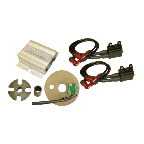
- Page 1 Quality SYSTEM TYPE: PDHG1 British Product Electronic Ignition Systems For Classic Road & Racing Applications SMARTーFIRE HIGH-PERFORMANCE IGNITION SYSTEM GOLDWING GL1000 PAZON : THE ULTIMATE SPARK PERFORMANCE...
- Page 2 SMART-FIRE APPLICATIONS • HONDA GL1000 FOUR CYLINDER FEATURES • HIGH-POWER PROGRAMMABLE DIGITAL IGNITION MODULE (FULLY ENCAPSULATED) • LOW POWER CONSUMPTION • FULLY PROGRAMMED IGNITION TIMING & COIL ENERGY CONTROL: IGNITION ADVANCE CURVE IS MAPPED TO SUIT THE GL1000 ENGINE • USER-PROGRAMMABLE REV.LIMITER BUTTON •...
-
Page 3: Important Notes
SMART-FIRE FITTING INSTRUCTIONS WARNING: THIS SYSTEM PRODUCES VERY HIGH VOLTAGES, ALWAYS SWITCH OFF BEFORE WORKING ON THE SYSTEM. IMPORTANT NOTES: BEFORE FITTING, PLEASE READ THESE INSTRUCTIONS CAREFULLY, INCLUDING THE NOTICE ON PAGE 16. This system is designed to work only with the special digital ignition coil provided with the system. - Page 4 There are two other wires connected to where the points plugged into. These wires go to the condensers mounted in front of the battery. Unplug both wires and tuck out of the way. The condensers are not required with this ignition system and should not be connected.
- Page 5 frame. This can be achieved by direct contact between the mounting brackets & screws, but if the mounting surface is non- metallic, plastic-coated or not connected directly to the frame, then an earthing wire should be provided. This would be a short wire with a ring/fork terminal at one end (placed under one of the mounting screw heads or nuts, or under the head of one of the module end plate screws) and a ring terminal at the other end...
- Page 6 Wiring (Please see wiring schematic on page 8) All connections should be made using good quality crimped or soldered connections; twisted wires will not give satisfactory operation. From the ignition trigger unit, feed the sleeved bi-coloured wires (white-black, white-red & violet-red) through the original aperture used for the contact-breaker wires and up to the ignition module.
- Page 7 This is a 12 volt output and provides 2 pulses per engine revolution (2 pulses/rev). If your tacho requires a different pulse rate, contact Pazon Ignitions. Connect to the tacho signal input terminal/wire. If you have a mechanical tacho, an inductive pickup tacho (e.g.
- Page 9 FIG. 3 FIG. 2 STEEL TIMING DISC & SPACER TUBE POINTS COVER OFF CONTACT-BREAKER ASSEMBLY & MECHANICAL ADVANCE UNIT COMPLETELY REMOVED. NOTE SMALL LOCATING PEG FIG. 4 TIMING DISC FITTED, ENSURE REAR SLOT ALIGNS WITH LOCATING PEG. SLIDE ON SPACER TUBE. FIT M6 WASHER &...
- Page 10 IGNITON TIMING (see figs. 7-11, pages 12-13) Switch off ignition. Set the engine to the static timing position, 5° BTDC. If necessary, slightly loosen the ignition trigger fixings so that it can be rotated by hand. Warning: risk of electric shock, keep hands &...
- Page 11 • Keeping the trigger in position, tighten the fixings. • Note the final position of the timing disc through the inspection hole. • If you make a mistake, switch the ignition off and restart from the beginning of step 4a (above). Switch off the ignition.
- Page 12 FIG. 5 FIG. 6 IGNITION TRIGGER TRIGGER FITTED INTO ASSEMBLY POINTS HOUSING. FIT M6 WASHERS & SCREWS SEE-THROUGH FIG. 7 VIEW OF HALL-EFFECT TIMING DISC TRIGGER DEVICE (TURNS (WIRES NOT SHOWN) ANTI-CLOCKWISE) RED STATIC INSPECTION TIMING LIGHT HOLE STEEL TIMING SET ENGINE TO DISC 5°...
- Page 13 FIG. 9 FIG. 8 TURN BASEPLATE SLOWLY TURN BASEPLATE SLOWLY ANTI-CLOCKWISE, CLOCKWISE UNTIL BACK TO START POSITION RED TIMING LIGHT RED TIMING LIGHT TURNS “OFF” BLINKS “ON” “OFF” FIG. 10 FIG. 11 TURN BASEPLATE SLOWLY TURN BASEPLATE SLOWLY CLOCKWISE UNTIL ANTI-CLOCKWISE UNTIL RED TIMING LIGHT RED TIMING LIGHT...
-
Page 14: Rev-Limiter
REV-LIMITER USE OF THIS FUNCTION IS AT YOUR OWN RISK, SINCE IT IS POSSIBLE TO SET THE REV-LIMITER TO BEYOND THE DESIGNED UPPER RPM LIMIT FOR YOUR ENGINE. SMART-FIRE ignition module features a function button that en- ables the user to set/reset the ignition rev-limiter. Unless specified when purchasing the system, the rev-limiter is not preset, allowing your engine to rev to its maximum (unrestricted). - Page 16 • Use of this product indicates your acceptance of this notice. • The product design, firmware & literature is Copyright © PAZON 2005-2006, & is protected under international copyright, trademark & treaty provisions. • To provide the best ignition systems possible, PAZON IGNITIONS reserves the right to alter &...
Need help?
Do you have a question about the PDHG1 and is the answer not in the manual?
Questions and answers