
Related Manuals for Becker VAU 1.1/1-AC


Summary of Contents for Becker VAU 1.1/1-AC
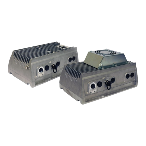
- Page 1 OPERATING INSTRUCTIONS - QUICK START GUIDE VAU 1.1/1-AC FREQUENCY CONVERTER MAKE IT BECKER...
-
Page 2: Table Of Contents
BECKER VAU 1.1/1-AC TABLE OF CONTENTS SAFETY INFORMATION WARNING SYMBOLS USED GENERAL INFORMATION COMMISSIONING INFORMATION OPERATING INFORMATION INTENDED USE INSTALLATION CONNECTION SPACE 2.1.1 CONNECTION POWER LINE 2.1.2 RELAYS 2.1.3 MOTOR CONNECTION 2.1.4 FAN CONNECTIONS 2.1.5 SIGNAL TERMINALS 2.1.6 PTC/BIMETALLIC SWITCH 2.2 RS485 INTERFACEE... -
Page 3: Safety Information
Visit our homepage for this: www.becker-international.com IMPORTANT INFORMATION This quick start guide represents only an excerpt of the VAU 1.1/1-AC operating instructions. The latter should be read thoroughly before initial start-up. The quick start guide contains safety instructions and helps the user to put the basic model of the frequency converter (FC) into operation and to operate it with the default settings. -
Page 4: Operating Information
BECKER VAU 1.1/1-AC DANGER Mortal danger from electric shock! Death or serious injury! Switch the frequency converter to zero potential and protect it against reactivation. The following terminals may still carry dangerous voltages even with the motor at rest: • mains connection terminals 1X1: PE, N, L •... -
Page 5: Intended Use
• Repairs may only be carried out by authorised repair centres. Independent unauthorised interventions may lead to death, personal injury and property damage. Such cases invalidate the warranty by Gebr. Becker GmbH. • No external mechanical loads, e.g. stepping onto the housing, are permitted! -
Page 6: Installation
BECKER VAU 1.1/1-AC VAU 1.1/1-AC → First steps INSTALLATION CONNECTION SPACE After opening the terminal box cover you will find all the connection terminals of the frequency converter in the connection area. Relay Mains supply Fan fuse PTC/bimetallic switch Rel.2: Collective fault message... -
Page 7: Connection Power Line
BECKER VAU 1.1/1-AC 2.1.1 CONNECTION POWER LINE Conductor cross-section of the mains power supply: 0,25 -4 mm (wire-end ferrule with plastic shroud) Stripping length: 12 mm Terminal Connection PE, N, L Mains supply - Conductor PE, N, L 2.1.2 RELAYS... -
Page 8: Signal Terminals
BECKER VAU 1.1/1-AC 2.1.5 SIGNAL TERMINALS Conductor cross-section of the signal lines: 0,5-1,0 mm (wire-end ferrule with plastic shroud) Stripping length: 9-10 mm Connection terminals of the bottom row of the double-decker terminal block: Terminal Connection 10V Out Int. voltage supply 10V 24V IN Ext. -
Page 9: Local Operation And Display
BECKER VAU 1.1/1-AC 2.3 LOCAL OPERATION AND DISPLAY The local operation of the device is done on the operating panel as shown. Potentionmeter LEDs indicate the Acknowledge button RS485 interface for adjusting the converter status Malfunktion setpoint Using the potentiometer (scale 0...100%), the current setpoint value can be increased or decreased. -
Page 10: Table Of Possible Error Messages
BECKER VAU 1.1/1-AC 3.2 TABLE OF POSSIBLE ERROR MESSAGES In case of a fault (red LED is permanently lit), the error is indicated via an extended flash code of the green LED. The green LED briefly flashes 1-10 times. At the end of the flash code there is a pause of 5 seconds before the code is repeated. The table below provides an overview. - Page 11 No voltage is present at the power Operation with 24 V without mains component supply System fault contact BECKER in case of this fault System fault contact BECKER in case of this fault System fault contact BECKER in case of this fault...
-
Page 12: Technical Specifications
BECKER VAU 1.1/1-AC TECHNICAL SPECIFICATIONS Description \ size VAU 1.1/1-AC Typical motor output [kW] to be connected (4 pole asynchronous motor) Mains voltage [V] 1~ 100VAC -10% ... 230VAC +10% Mains frequency [Hz] 47 to 63 Grid configuration TN / TT Mains current [A] FC output current, eff. -
Page 13: Interfaces
BECKER VAU 1.1/1-AC INTERFACES Inputs and outputs Description Digital input 1...3 • Switching level Low < 5 V / High > 15 V • I (bei 24 V) = 3 mA • R = 8,6 kOhm Analog input 1...4 • In 0 – 10 V or 0 – 20 mA •... - Page 14 MAKE IT BECKER...
Need help?
Do you have a question about the VAU 1.1/1-AC and is the answer not in the manual?
Questions and answers