
Subscribe to Our Youtube Channel
Related Manuals for Ntron SIL O2


Summary of Contents for Ntron SIL O2
- Page 1 SIL O Oxygen Analyser User Operation Manual Rev. 1.1 P a g e R e v . 1 . 1 30/11/2018 I s s u e 3 0 - 1 1 - 2 0 1 8...
- Page 2 P a g e R e v . 1 . 1 I s s u e 3 0 - 1 1 - 2 0 1 8...
-
Page 3: Table Of Contents
Possible Sensor Faults ........................21 General Maintenance .......................... 22 Specifications..............................23 Appendices ..............................26 SIL O2 Analyser and Sensor Connection Diagrams ................27 SIL O2 Analyser CE and ATEX Certificates ..................28 Sensor CE and ATEX Certificates ...................... 29 P a g e R e v . - Page 4 Revision History Revision No. Change Description Date First Issue 19-10-2018 Note added for Non-ATEX Sensor usage 22-10-2018 Reference to 15% O2 in trouble shooting section removed. 30-11-2018 Calibration Span instruction amended and note added P a g e R e v . 1 . 1 I s s u e 3 0 - 1 1 - 2 0 1 8...
- Page 5 P a g e R e v . 1 . 1 I s s u e 3 0 - 1 1 - 2 0 1 8...
-
Page 6: Introduction
Note. Non-Atex (Ex) Sensors variants of the models listed in the manual may also be used with the SIL O2 Analyser as long as they are installed in a Non-ATEX (Ex) or ‚Safe‘ area or zone. -
Page 7: Installation And Operation
Sensor options are detailed in the Specification section of this manual. If the SIL O2 Analyser has been supplied with a Sensor, the two units will have been calibrated at the Ntron factory prior to delivery. Otherwise, if a Sensor is supplied separately from the SIL O2 Analyser, a calibration will be required prior to putting the system into operational service. - Page 8 The Ntron Sensors suitable for use with the SIL O2 analyser are listed in the Installationn section which follows. P a g e R e v . 1 . 1 I s s u e 3 0 - 1 1 - 2 0 1 8...
- Page 9 The SIL O2 oxygen analyzer is an associated explosion-proof [Ex ia] IIC or [Ex ib] IIC electrical device and should always be used outside potentially explosive areas (in a safe area). Only electrical circuits, certified as intrinsically safe, can be connected to other intrinsically safe circuits in the Ex zone.
-
Page 10: Installation
Specification section of this manual. The SIL O2 analyzer is designed for DIN rail mounting and can be supplied mounted in an additional enclosure or provided without an additional enclosure for customer mounting in a system enclosure or control panel. -
Page 11: Electrical And Interface Connections
2.3.1 Sensor Input and Customer Interface Wiring The Ntron ATEX Sensor selected for use with the SIL O2 Analyser as listed in the Installation section previously, has intrinisically safe parameter values which match the Isolation Barrier output which is built into the SIL O2 Analyser. -
Page 12: Operational Settings And Wiring Configuration
SIL O2 Analyser and Sensor unit will detail these settings. See the Ntron SIL O2 Technical and Safety manual for further details. The SIL O2 Analyser has a main trip Relay referred to as RL3. This is not programmable and is normally open(contacts)/de-energised when the Analyser is not under power. The Relay energises and its associate contacts close when power is applied and the Analyser and Sensor are healthy and ready to operate. -
Page 13: Typical Relay Configuration
This range can not be adjusted. If the 4-20 mA output is not used, the SIL O2 terminals T11 and T12 must be wired by the user. This output is internally connected in series with the SIL O2 Analyzer digital display, which will not work if the... - Page 14 14 | P a g e R e v . 1 . 1 I s s u e 3 0 - 1 1 - 2 0 1 8...
-
Page 15: Sensor Process Connection Options
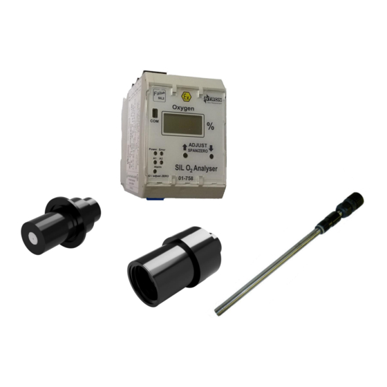
2.3.4 Sensor Process Connection options The Sensors are suitable for mounting directly onto process Tri-Clamp Sensor Base Lines via a selection of process fittings. The electrical signal connectors are rated to IP67. OC-25 Sensor Flow Through Sensor Base OC-26 Sensor KF40 Process fitting KF40 Process fitting onto pipeline OC-200 Sensor with Screwed Bush Process fitting... -
Page 16: Operation
20.9% O2. It is possible to also adjust the Zero point of the SIL O2 Analyser. Typically this would only be required when fitting a new/replacement Sensor. A Complete calibration procedure is given below. -
Page 17: Setting The Zero Point
The sensors to be used with the SIL O2 unit will generally give a small output at zero oxygen levels. The zero adjustment function allows the user to adjust this small signal so that the SIL 2 analyzer displays 0.0 when no... -
Page 18: Span Calibration
2.4.3 SPAN Calibration This can be done periodically or as needed in accordance with the requirements of the calibration protocol. Calibration can be performed by applying either clean ambient air or a 20.9% certified oxygen rate to the sensor. Note: •... -
Page 19: Operational Safety And Maintenance Instructions
3.1 Fault conditions The SIL O2 Analyzer failure operation is not locked out by a fault. When a fault condition is repaired, the trip relay RL3 and the red fault indicator will return to their "healthy" or "operational" state after a few seconds following an automatic internal cyclic check. -
Page 20: Troubleshooting
3.4 Troubleshooting Possible Faults and their solutions The following possible conditions are applicable to a system (Sil Analyser and Sensor) already installed and commissioned. Some conditions below may also be applied to new systems not yet commissioned. • Action: Performing a Zero calibration when the Oxygen Sensor is in ambient air. Problem: An incorrect Zero level input to the Analyser will result in an overrange fault. -
Page 21: Possible Sensor Faults
Solution: Sensor is at end of life. Sensor has been wetted or contaminated. The Sensor output signal can be checked at the SIL O2 Analyser terminals 14 and 16. See specification section for details of a healthy output signal. Problem:. -
Page 22: General Maintenance
The SIL O2 Analyser requires little physical maintenance. The user Enclosure into which it is housed should provide protection against a build up of dust or other contaminants on the surface of the SIL O2 Analyser housing. If such contaminants are seen during regular inspection, such can be removed by gentle suction device or by wiping with a damp but not wet, cloth. -
Page 23: Specifications
4. Specifications SIL O2 Analyser Specifications-Electrical Supply Voltage 24VDC +/- 10% Supply Power 1.5 Watt Analogue Output 4-20mA active source. 22mA Max output . Load 390 Ohm@22mA, Max 420 Ohm@20mA constant current. Communications RS232/Com 9600bps Relay Contact outputs Um 125VAC/110VDC (Typically 30VDC)@ 1Amp. Min Current 10uA RL1/RL2/RL3 DC. - Page 24 Certification/Standards CE, ATEX 2014/34/EU/ EN 60079-0:2012 + A11:2013, EN 60079- 11: 2012, EN 60079-26: 2015 0158 II (1) G II (1) D ; [Ex ia Ga] IIC; [Ex ia Da] IIIC Functional safety: SIL2 according to IEC 61508/61511 EMC 2014/30/EU EN 61326-3-2:2008;...
- Page 25 Protection Class IP67 When inserted into process fitting with Connector fitted. Process Connection OC-25 =Ntron Sensor base; OC-26 = KF40 Flange, OC-200 = Probe Holder mechanism or Bushing Weight OC-25= 250g; OC-26=150g, OC-200=180g Environmental Temperature: -20 to +45-50°C, 10-95% Humidity, no condensation.
-
Page 26: Appendices
5. Appendices • SIL O2 Analyser and Sensor Connection Diagrams • SIL O2 Analyser CE and ATEX Certificates • Sensor CE and ATEX Certificates 26 | P a g e R e v . 1 . 1 I s s u e 3 0 - 1 1 - 2 0 1 8... -
Page 27: Sil O2 Analyser And Sensor Connection Diagrams
5.1 SIL O2 Analyser and Sensor Connection Diagrams • E364 SIL O2 with OC-25 Sensor • E511 SIL O2 with OC-26 Sensor • E395 SIL O2 with OC-200 ‘Oxyprobe’ 27 | P a g e R e v . 1 . 1... - Page 33 5.2 SIL O2 Analyser CE and ATEX Certificates • CE Certificate CETX003 • ATEX Certificate Dekra BVS 13 ATEX E 010 28 | P a g e R e v . 1 . 1 I s s u e 3 0 - 1 1 - 2 0 1 8...
- Page 34 EU Declaration of Conformity/ EG-Konformitätserklärung/ Déclaration de conformité CE/ Declaración de conformidad CE Dichiarazione di conformità En: We declare, under our full responsibility, that we believe the products identified in this declaration, and to which this declaration relates are in conformity with the requirements of Council Directives: D: Wir erklären unter unserer vollen Verantwortung, dass wir glauben, dass die Produkte in dieser Erklärung identifiziert, auf die sich diese Erklärung bezieht, in Übereinstimmung mit den Anforderungen der Richtlinien: Fr: Nous déclarons, sous notre entière responsabilité, que nous croyons que les produits identifiés dans la présente Déclaration, et à...
- Page 35 David Beirne Title/Position; Titel / Position; Titre / Position; Título / Puesto; Titolo / Ruolo : Managing Director/Geschäftsführer /Directeur Général/ Director Gerente/Amministratore Delegato Address/Anschrift/ adresse/ dirección/indirizzo Ntron Ltd, Mullaghboy Industrial Park, Navan, Co. Meath, Ireland. Signature Date: 25/02/2019 Rev. 1.5...
-
Page 46: Sensor Ce And Atex Certificates
5.3 Sensor CE and ATEX Certificates • CE Certificate SUII01, SUII02 • ATEX Certificate BAS02ATEX1230X-11 29 | P a g e R e v . 1 . 1 I s s u e 3 0 - 1 1 - 2 0 1 8... - Page 47 SK17 9RZ, UK. Notified Body Number: 1180 The Authorised Signatory to this declaration, on behalf of the manufacturer, is identified below: Name: David Beirne Title/Titel/ Titre/ título: Managing Director/Geschäftsführer/Directeur-Général/director Gerente Address/Adresse/ dirección: Ntron Ltd Ph: 00353469071333 Mullaghboy Industrial Estate Fx: 00353469071331 Navan email: info@ntron.com...
- Page 51 El signatario autorizado a esta declaración, en nombre del fabricante, se identifica a continuación: Name: David Beirne Title/Titel/ Titre/ título: Managing Director/Geschäftsführer/ Directeur- Général/ director Gerente Address/Adresse/ dirección: Ntron Limited Mullaghboy Industrial Estate Navan Co. Meath Ireland, C15 XD61 Signature:...
- Page 56 Ntron Ltd. Mullaghboy Industrial Estate, Navan, County Meath, Ireland. 00353 46 9071333 www.ntron.com 30 | P a g e R e v . 1 . 1 I s s u e 3 0 - 1 1 - 2 0 1 8...
Need help?
Do you have a question about the SIL O2 and is the answer not in the manual?
Questions and answers