Advertisement
Advertisement
Table of Contents

Subscribe to Our Youtube Channel
Related Manuals for SunDash 20 GENESIS System 332 Pro-1

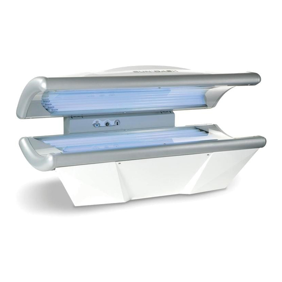
Summary of Contents for SunDash 20 GENESIS System 332 Pro-1
-
Page 2: Specifications
Specifications Length: 85” Width: 41” Height: 39.8” - 49.6” No. of Lamps: 32 Low Presure & 1 High Presure Electrical: 120/208VAC and 120/240VAC Circuit Required: 20 Amp Breaker DANGER - ULTRAVIOLET RADIATION. FOLLOW INSTRUCTIONS. AVOID OVEREXPOSURE. AS WITH NATURAL SUNLIGHT, OVEREXPOSURE CAN CAUSE EYE AND SKIN INJURY AND ALLERGIC REACTIONS. -
Page 3: Warnings And Cautions
Warnings and Cautions Certain drugs - particularly those that It is recommended that only one person p r o d u c e p h o t o s e n s i t i v i t y - m a y c a u s e at a time should use the tanning system while individuals under the influence of this type drug in use, and advises using protective eyewear... -
Page 4: Skin Types
Care and Cleaning of Your Tanning Unit After each session is completed, spray the cloth because this will generate a slight static acrylic surface with specially formulated UVT charge which will attract dust. A mild liquid (ultraviolet transmitting) acrylic cleaner. Wipe detergent and water solution can be used the surface of the acrylic with a clean cloth. - Page 5 PACKAGING The ta nning system is shipped in three separate boxes. The type of assembly in each box is labeled on the outside. The box containing the tanning system legs is placed on top, followed by the box containing the base and then the box containing the canopy.
- Page 6 FASTENER ILLUSTRATIONS 5/16 Hex Washer Nut ¼ - 20 Hex Nut Phillips Screw #6 X 3/8 Flat Washer Phillips Truss Head Screw ¼ X 20...
- Page 7 CONTENTS POWER BOX COVER POWER MIDDLE FACADE FRONT FACADE BASE CANOPY...
-
Page 8: Tools Required For Assembly
ASSEMBLY ASSEMBLY To avoid personal injury and or damage to the tanning system, it is recommended that the tanning system be assembled by a minimum of two persons. All electrical connections inside the tanning system should be completed by a Certified Electrician or a Factory Authorized Representative. -
Page 9: Leg Installation
LEG INSTALLATION Remove packing and leg assemblies from the carton marked LEG ASSEMBLIES. Position leg assemblies in the desired location. The leg assemblies are in the shape of a boomerang and should face outward away from the wall with support brackets facing the middle. -
Page 10: Canopy Installation
CANOPY INSTALLATION Remove packing and unit from box marked TOP UNIT. Lift top into position (acrylic facing down). The bolts should protrude through the holes of the mounting bracket in the leg assemblies. The canopy is secured to the leg assemblies using eight (8) 5/16”... - Page 11 Bed Connections CANOPY AND BASE The power cords from the canopy and base are plugged into bottom of relay enclosure. The illustration to the left indicates the position of each wire. FACIAL The power cord (on tanning systems with a facial lamp) for the facial assembly is equipped with plug.
- Page 12 BUCK-BOOST TRANSFORMER BUCK-BOOST TRANSFORMERS SHOULD NEVER BE USED TO BOOST POWER BEING SUPPLIED TO ENTIRE TANNING SYSTEM. POWER TO THE FACIAL TANNER CIRCUIT SHOULD ONLY BE BOOSTED WHEN REQUIRED (SEE EXPLANATION BELOW). The use of Buck-Boost transformers is NOT REQUIRED on units that do NOT have a facial tanner. A Buck-Boost transformer is not required for tanning systems with a facial tanner being installed in locations where the incoming power is 240V.
-
Page 13: Wire Connections
WIRE CONNECTIONS The illustration below shows the placement of each wire in the power box. ALL ELECTRICAL CONNECTIONS INSIDE OF TANNING SYSTEM MUST BE COMPLETED BY FACTORY AUTHORIZED PERSONNEL OR LICENSED ELECTRICIAN. CONNECTIONS TO THE ELECTRICAL SERVICE MUST BE COMPLETED BY LICENSED ELECTRICIANS ONLY. - Page 14 To install front façade, center the facade with the tanning system and position it in close proximity with the bottom of each leg. Align the clips on the bottom of the facade with the receptacles on each leg (one person can lift, install, and secure the “Front Façade”...
- Page 15 ACRYLIC REMOVAL & INSTALLATION Quarter turn fasteners are used to secure the acrylic to the canopy. A standard screw driver should be used to remove each of the six ¼ turn fasteners. The location of the ¼ turn fasteners are indicated by the arrows on the illustration on the left.
-
Page 16: Lamp Removal
LAMP REMOVAL To remove lamps, rotate 90 and lift out. LAMP INSTALLATION To install lamps, position pins inside lamp holder as illustrated and rotate . Lamp etching should always be visible to tanner after installation. - Page 17 CANOPY (SERVICE PARTS EXPLOSION)
- Page 18 NOT A SERVICE ITEM 0000735044 HP FACIAL FILTER GLASS NOT A SERVICE ITEM 0032002410 AXIAL FAN (105 CFM) 120V NOT A SERVICE ITEM 0000550046 ACRYLIC, SUNDASH 32 0000012842 LAMP 59” (100 W) 0000012843 LAMP 71” (120 W) NOT A SERVICE ITEM...
- Page 19 BASE (SERVICE PARTS EXPLOSION) BASE (SERVICE PARTS) PART NO DESCRIPTION NOT A SERVICE ITEM 0031002482 BALLAST ELECTRONIC SMART CELL 0032002410 AXIAL FAN (105 CFM) 120 V NOT A SERVICE ITEM NOT A SERVICE ITEM 0000050408 LAMP HOLDER W/O STARTER (BLACK) NOT A SERVICE ITEM 0000012843 LAMP 71”...
- Page 20 LEG & MIDDLE FAÇADE (SERVICE PARTS EXPLOSION)
- Page 21 LEG & MIDDLE FAÇADE (SERVICE PARTS) PART NO. DESCRIPTION NOT A SERVICE ITEM NOT A SERVICE ITEM NOT A SERVICE ITEM 0030002684 AMP, RECEPT 120V 0038002114 HOUR METER, DIGITAL NOT A SERVICE ITEM NOT A SERVICE ITEM NOT A SERVICE ITEM 0055006126 SPRING 110# 0039002153...
- Page 22 ADDITIONAL SERVICE PARTS Description Part Number Timer TIMER,ELO5 0038003001 Label TIMER LABEL 0050005482 LOGO LABEL 0050005451 Button FACIAL ON/OFF SWITCH 0000011566 RHEOSTAT 0032002252 Igniter/Capacitor IGNITE R, 100-400W FACIAL 0000010535 Limit Switch MICRO LIMIT SWITCH 0036002605...
- Page 23 TIMER USER’S GUIDE ® This tanning system is equipped with a digital timer that has the T-MAX communication protocols built in. The timer will allow the tanning system to operate in stand-alone mode or be placed on a digital timer network. In addition the timer also supports wireless technology.
- Page 24 4) To observe the current value of a parameter, press the START/STOP button. The Display will show a number with a period in the lower center of the display. The numbers will be flashing. The number shown is the current value for that parameter (see illustration A).
- Page 25 6) Press the START/STOP Button. The display will show the parameter number you just changed and a solid period in the lower center of the display. Nothing will be flashing. You may now change another parameter by pressing the UP and DOWN buttons until the parameter you want displayed.
- Page 26 Table 1 - Parameter Numbers for Observing and Changing Parameters. * If Manual Lockout is enabled, the timer cannot operate as a stand-alone timer. In the event of a timer failure, this parameter cannot be enabled at the timer. Parm # Description Max # Default...
- Page 27 Setting Delay Time. 1) Press and hold the START/STOP and UP buttons at the same time until a .1 appears on the display. This should take about 5 -6 seconds. Release the buttons. 2) Press the UP button until a .3 is displayed. 3) Press and release the START/STOP button.
- Page 28 Interfacing with Digital Room Controllers 1) Connect the timer to the tanning bed as described. 2) Set the address on each timer as described in “Setting the Address Section”. 3) Connect timers to the bed network. Connect the Digital Tanning System Controller to the closest timer.
- Page 29 JK Products & Services Limited Warranty JK Products & Service warrants its products to be free from defects in materials and workmanship under intended normal use as described in the unit’s Operation and Instruction Manual, for a period of one (1) year from date of sale. This Limited Warranty applies only to the original purchaser of the equipment through JK Products &...
-
Page 30: Limited Acrylic Warranty
Limited Acrylic Warranty JK Products & Service warrants its acrylic sheets to be free from defects in material and workmanship, under intended normal use, for a period of one (1) year from date of sale of the tanning bed. Due to the tanning lotions, cosmetics, disinfectant and improper cleaners used on tanning surfaces that cannot be controlled by JK Products &... -
Page 31: Warranty Claims
Warranty Claims Policy & Procedures When to file a Warranty Claim: In the event that your tanning system is not functioning properly under intended normal use as described in the unit’s Operation and Assembly Manual, you may then have established cause to file a Warranty Claim.
Need help?
Do you have a question about the 20 GENESIS System 332 Pro-1 and is the answer not in the manual?
Questions and answers
Bought this model from a salon and can’t get it to work in my home. any trouble shooting advice?
The available troubleshooting advice for the SunDash 20 GENESIS System 332 Pro-1 includes:
1. Canopy Installation: Ensure the bolts of the canopy rest against the top of the holes in the mounting bracket of the leg assembly. Failing to do so may cause the canopy to close improperly and not remain open. It is recommended to have two individuals install the canopy, with a third person simplifying the process.
2. Power Connections: The power cords from the canopy and base should be plugged into the bottom of the relay enclosure. Ensure proper positioning of each wire as indicated in the manual.
3. Facial Lamp Power: If the tanning system includes a facial lamp, its power cord is equipped with a plug. For 208V single/three-phase configurations, a Buck-Boost transformer is required to boost power to the facial lamp circuit. However, the transformer should not be used to raise the operating voltage of the entire tanning system.
These steps ensure proper installation and operation of the system.
This answer is automatically generated
How do you reset the timer from saying help #2