Table of Contents
Advertisement
EAS-1/EAS-1CG Setup and Operation
Table of Contents
Section I: EAS-1/CG Description..............................................................................................................2
Section II: Setting up the EAS-1/EAS-1CG.............................................................................................8
Section III: Setting up the EAS-1/EAS-1CG............................................................................................9
Section IV: EAS-1/EAS-1CG Operating Display...................................................................................10
Section V: EAS-1/EAS-1CG Keypad Options........................................................................................13
Section VI: Sending an Alert...................................................................................................................19
Section VII: EAS-1/CG On-Screen Utility Menu...................................................................................21
Section VIII: Using the EAS-1/CG Utility Menu...................................................................................23
Section IX: Cable Setup..........................................................................................................................35
System Setup Menu.............................................................................................................................38
SYSTEM TESTS................................................................................................................................41
Setup in the Cable SSC Mode.............................................................................................................42
SETUP SSC SYSTEM........................................................................................................................42
SYSTEM TESTS................................................................................................................................45
Section X: Station Setup in the EAS-1/EAS-1CG..................................................................................46
1. Operator Password..........................................................................................................................46
2. Technician Password.......................................................................................................................47
3. Call Letter Entry..............................................................................................................................48
4. State Primary Selection...................................................................................................................49
5. Station Time Zone Selection...........................................................................................................50
6. Daylight Time Selection..................................................................................................................50
7. Originator Code Selection...............................................................................................................51
8. State and County Selection..............................................................................................................51
Section XI: EAS-1/EAS-1CG DTMF Telephone Interface....................................................................58
GORMAN REDLICH
257 West Union St.
Athens, Ohio 45701
FAX: 740-592-3898
Ph: 740-593-3150
Manual
Advertisement
Table of Contents

Related Manuals for Gorman-Redlich EAS-1


Summary of Contents for Gorman-Redlich EAS-1
-
Page 1: Table Of Contents
Section IV: EAS-1/EAS-1CG Operating Display...................10 Section V: EAS-1/EAS-1CG Keypad Options..................13 Section VI: Sending an Alert........................19 Section VII: EAS-1/CG On-Screen Utility Menu...................21 Section VIII: Using the EAS-1/CG Utility Menu...................23 Section IX: Cable Setup..........................35 System Setup Menu..........................38 SYSTEM TESTS..........................41 Setup in the Cable SSC Mode......................42 SETUP SSC SYSTEM........................42... -
Page 2: Section I: Eas-1/Cg Description
Section I: EAS-1/CG Description EAS-1/CG Encoder Specifications Access Control: Access to the encoder to generate an alert is protected against unauthorized personnel generating false alerts by requiring a four-digit access code which must be entered from the front panel keypad or optional telephone interface. The four-digit code is not required if the encoder is being programmed through the DB9 RS232 PC port or when a valid incoming alert is being manually forwarded. - Page 3 C - +60 Gorman-Redlich EAS-1/CG Decoder Specifications Audio Inputs: The EAS-1/CG decoder section provides six audio inputs which greatly exceeds the FCC specification of two audio inputs from EAS monitoring assignments. It also has a DB9 RS232 data input port which operates at 1200 baud.
-
Page 4: Other Specifications
4-line, 40-character, LED backlit display. The audio message portion of an alert is heard on the front panel speaker. The EAS-1/CG also monitors each of the audio inputs and presents a visual indication of whether or not the audio is present on each channel. - Page 5 • Optional telephone jack for telephone control (requires installation of optional internal DTMF telephone interface board) . EAS-1/CG Rear Panel Description The rear panel of the EAS-1/CG has an array of ports of various types. On the top, from the right, are four RS232 ports: • COM3: Modem (male RS232/DB9) •...
- Page 6 EAS-1/CG Rear Panel Terminals Six pairs of audio inputs are each coupled to the decoder by 600 ohm to 1-12 Audio In-Monitors 1-6 600 ohm isolation transformers. These six audio sources are scanned for EAS alert messages. 13-14 Audio Out 600 Ohm...
- Page 7 weekly test; FSK header code and EOM) Momentary contact closure input to remotely send RMT (required 47-48 Control In - RMT monthly test; FSK header and dual tones) 49-50 Data In/Out - RS485 Serial data option for future remote control equipment. 51-52 Spare terminals Can be used to supply battery backup power to the unit.
-
Page 8: Section Ii: Setting Up The Eas-1/Eas-1Cg
2. We strongly recommend placing the EAS-1/CG on an uninterruptible power supply (UPS). The printer and the receivers used to monitor the National Weather Service and/or broadcast stations should also be plugged into this. -
Page 9: Section Iii: Setting Up The Eas-1/Eas-1Cg
Section III: Setting up the EAS-1/EAS-1CG NOTE: The DOS EAS Setup software has been replaced by a new Windows compatible setup program. Check the Gorman Redlich website for the instruction manual for the new software version (PDF reader required). -
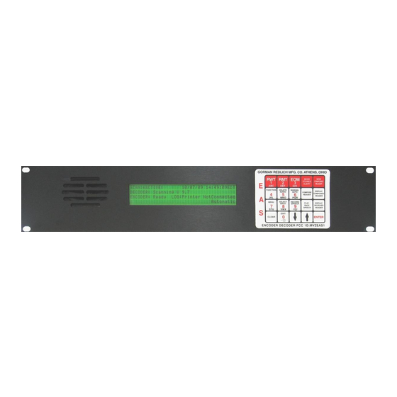
Page 10: Section Iv: Eas-1/Eas-1Cg Operating Display
The first two figures show the display with the TV/CG message in the lower right-hand corner, which is the normal operating mode for the EAS-1/CG. However, the unit can operate in other modes. When the unit is in regular ("PSC") Cable mode, the front screen will show it as follows: Figure IV.3... - Page 11 PC port, or when no logging is chosen. There are only four printer states possible as shown on the display. The second is when the EAS-1/CG is logged to the printer, and the printer is connected but is not operating properly. Then a screen will be shown as below, with the PRINTER UNKNOWN ERROR message.
- Page 12 The third mode is PRINTER NOT CONNECTED, which occurs when PRINTER is not selected for logging (menu item 7), or when PRINTER is selected but no cable is connected, or when there is no functioning data connection between the EAS-1/CG and the printer for some other reason.
-
Page 13: Section V: Eas-1/Eas-1Cg Keypad Options
Section V: EAS-1/EAS-1CG Keypad Options The EAS-1/EAS-1CG keypad layout is as follows: Figure V.1: EAS-1/EAS-1CG Keypad Layout SEND SEND STORED COMPOSED ALERT HEADER FUNCTION DELETE MANUAL COMPOSE DISPLAY AUDIO AUTO COMPOSED HEADER HEADER MENU SELECT RECORD PLAY- DISPLAY INPUT SPEECH... - Page 14 <SEND COMPOSED HEADER>: Originate an alert: This key, when pressed, acts like the <RMT> key but sends the composed header rather than RMT. After the three FSK bursts and the attention tone, the unit again outputs audio, either from a studio mike or pre-recorded. Again, when the audio message is finished, EOM must be pressed to complete the test.
- Page 15 the display. Fourth Row The bottom-row keys are used only in conjunction with other operations, and do not themselves initiate any operations. <CLEAR>: This key is only used in a few instances, and will be prompted for when applicable. <EXIT>: This key is always used for backing out of menu items and selections, reversing the selection process.
- Page 16 This function enables the operator to see if editing of the header code is necessary prior to its sending: Figure V.9 ****** EAS ALERT SENT BY EAS-1/CG ****** SENT 4/18/2000 9:54:58 EDT...
- Page 17 <Select Input>: This is used to monitor audio inputs through the front panel speaker. By using the <\/> to move the cursor and pressing the <ENTER> key, the audio on each input can be monitored on the EAS-1/CG front panel speaker. It uses this screen: Figure V.10...
- Page 18 Figure V.13 **** EAS ALERT RECEIVED BY EAS-1/CG **** CH# 3 RECEIVED 4/18/2000 9:54:58 EDT A BROADCAST STATION HAS ISSUED A TORNADO WARNING FOR THE FOLLOWING COUNTIES:...
-
Page 19: Section Vi: Sending An Alert
Upon completion of the emergency message send the end of message by pressing the <EOM> key. If you forget to send the EOM message, the EAS-1 will automatically send the EOM after two minutes. - Page 20 them. In Broadcast Automatic mode, they will be sent according to the priority set for them, but you may send them manually any time within the priority time period. In fact, this is why the priority time period exists: for you to select an appropriate time to send the alert manually to minimize program interruption.
-
Page 21: Section Vii: Eas-1/Cg On-Screen Utility Menu
Section VII: EAS-1/CG On-Screen Utility Menu Press the <MENU> key on the keypad of your EAS-1/CG unit. You will be prompted for a four-digit password. On the keypad, enter the four digits of your technician passcode. The utility menu will then appear on the display, showing menu items numbered 1 through 6. If you press the <\/>, you will scroll down through the items, then you will go to a second screen,... - Page 22 15 AUDIO REC/PLAYBK 16 PHONE SETUP 17 STATION SETUP 18 FUTURE EXPANSION Most values that can be set through the Utility Menu can be printed out in a summary list through option 8, PRINT SETUP DATA: FRONT PANEL SETUP.
-
Page 23: Section Viii: Using The Eas-1/Cg Utility Menu
Section VIII: Using the EAS-1/CG Utility Menu To select any utility menu option shown on the screens in figures VII.1 - VII.4, use the<\/> to move the cursor to the desired parameter and press <ENTER>. Option One: SET DIAGNOSTICS When you select this option, this screen will appear: Figure VIII.1... - Page 24 < DOWN ARROW UP ARROW > SETTING: Note that there is a numerical setting shown in the lower-right-hand corner which represents the digital pot setting, from 1 to 100. Setting 8 is the default for 853 Hz and 960 Hz. Setting 17 is the default for 1562.5 Hz and 2083.3 Hz.
- Page 25 ######################## ^ MIN |-----|-----| MAX ^ RELATIVE LEVEL < DOWN ARROW UP ARROW > SETTING: This option functions identically to the SET MODULATION. Note that there is a numerical setting in the lower-right-hand corner, which again represents the digital pot setting from 1 to 100.
- Page 26 NOTE: Read this carefully; many people find this option confusing. Note that the first example only has two channels selected, with no selection for NWS, National Weather Service. The second example has all six channels selected, with the National Weather Service on channel 3.
- Page 27 PRINTER NOT CONNECTED. The output is, of course, directed to the PARALLEL PRINTER port on the rear of the EAS-1/CG, which mates to a normal printer cable. If this option is set to PC SERIAL PORT, then I/O is directed through the P.C. PORT (female RS-232 DB9) on the rear of the EAS-1/CG.
- Page 28 By selecting option one by pressing <1> on the EAS keypad (after pressing <ENTER> for option 8), the printer will print out the EAS-1/CG programming on two pages. Select option two by pressing <2> on the keypad. This will print out the information selected by the EAS menu items, including the input channel levels and modulation levels.
- Page 29 10 TOGGLE CG Figure VII10.0a 10 TOGGLE CG Figure VII10.0a 10 NON-CABLE OPTION If the first, TOGGLE CG ON, is showing, then the character generator is turned off, and selecting this option by pressing <ENTER> will result in this screen, and the generator will then be turned on: Figure VIII.10.1 CHARACTER GENERATOR IS NOW ON...
- Page 30 This option toggles the alert relay momentarily on when operating in Manual mode. This relay is connected to terminals 19-22 on the terminal plug on the rear of the EAS-1/CG unit. This option works identically to menu items ten and eleven. The menu screen that includes option twelve may show either one of the following legends for the option: Figure VIII.12.0a...
- Page 31 Figure VIII.12.1 ALERT RELAY IN MANUAL IS NOW ON PRESS EXIT TO EXIT If the second, TOGGLE SIGN OFF, is showing, then the sign board is turned on, and selecting this option by pressing <ENTER> will result in this screen, with the sign board turned off: Figure VIII.12.2 ALERT RELAY IN MANUAL IS NOW OFF...
- Page 32 >0:15 0:30 0:45 1:00 1:30 2:00 2:30 3:00 3:30 4:00 4:30 5:00 5:30 6:00 This next option only applies to RMT messages that are received by EAS units in AUTOMATIC mode. The SEND NOW option means that, when the RMT is received at your station, the EAS unit will automatically and immediately interrupt programming to relay the test.
- Page 33 RECORD SPEECH KEY TO RECORD PLAYBACK SPEECH KEY TO PLAYBACK EXIT KEY TO EXIT When ready to record, press the <RECORD SPEECH> key on the EAS-1/CG keypad. You will then see this screen: Figure VIII.15.2 ---CANNED AUDIO REC/PLAYBCK - SPEAKER---...
- Page 34 > PHONE SUPPORT IS ON , ENTER TO CHANGE PHONE PARAMETERS, ENTER TO CHANGE Pressing <ENTER> on either one of these screens will toggle is to the other screen--in other words, if phone support is off, pressing <ENTER> will turn it on, and vice versa. If you use the <>...
-
Page 35: Section Ix: Cable Setup
The second option here, RE-SEND/IGNORE INCOMING RWT, is only applicable if cable mode is turned on. In cable mode, this means that the EAS-1/CG will or will not forward the code for the incoming RWT to the auxiliary computer, but does not automatically cause the signal to be re-sent over the outgoing line, although this is possible at the operator's discretion. - Page 36 ARROW TO SET, EXIT TO EXIT CABLE SUPPORT IS SSC, ENTER TO CHANGE _ CABLE/CG SETUP MENU , ENTER TO CHANGE If the SSC setup is selected, the following screen will appear: Figure IX.0.5 SETUP SSC CABLE SUPPORT 1 CHAR. GEN. SETUP 2 SYSTEM SETUP 3 SYSTEM TESTS 4 FUTURE...
- Page 37 Figure IX.1.2.0 CRAWL REPEAT 1 CRAWL REPEAT, FULL SYSTEM ACCESS 2 CRAWL REPEAT, EAS CHANNEL This allows y you to select the number of continuous crawls that will repeat for each set. For instance, if you select five crawls, then the alert message will crawl five consecutive times without a pause, then there will be a break, set by the previous menu option, after which there will again be five consecutive and continuous crawls, and so forth for the duration of the valid time of the alert.
-
Page 38: System Setup Menu
IS TEMPORARILY OFFLINE DUE TO TECHNICAL DIFFICULTIES 4. Character/Background Colors The fourth option, CG CHAR/BKG COLORS, brings up this screen: Figure IX.1.4 CG CHARACTER/BACKGROUND COLORS Black Characters, Gray Background >White Characters, Black Background White Characters, Gray Background The default value for this is the second selection, white characters on a black background. This gives maximum contrast. - Page 39 5 EAS CHAN BACKGND 6 RELAY MAPPING 1. Display Non-Required Events Selecting the first option, DSPLY NON-REQ EVT (Display Non-Required Events) brings up this screen: Figure IX.2.1 DISPLAY NON-REQUIRED EVENTS ARROW TO SET, EXIT TO EXIT >On All Channels On EAS Channel Only TUNE TO Msg on All Channels This is for a multichannel setup.
- Page 40 MNO sequence. To produce a 5, press the <5> then the <4>. For another example, to enter EAS-1, the key sequence would be: 2-2, 1-1, 7-1, 0-1, 1-4. To produce a space, however, you only need to press the <\/>. The </\> will backspace to erase errors.
-
Page 41: System Tests
This may also read: Figure IX.2.4.2 WEEKLY TEST SETUP 1 RE-SEND INCOMING RWT The setting specified on the screen is the active setting. Press <EXIT> to return to the TV setup screen. Press <EXIT> again to return to the Setup TV/CG Support screen. SYSTEM TESTS The third menu under SETUP TV/CG SUPPORT is SYSTEM TESTS. -
Page 42: Setup In The Cable Ssc Mode
Setup in the Cable SSC Mode Although you probably will never use this mode, we're including the setup instructions for everything this unit is programmed for. Crawls per Repeat In the Cable SSC mode, this is a little different from the TV/CG mode--there are two options under this selection. - Page 43 2. Enter System Name This works exactly like the same option in TV/CG mode, except that the default system name for Cable SSC mode is YOUR LOCAL CABLE TV SYSTEM. 3. EAS Channel Number The third menu item, EAS CHANNEL NO., results in this screen: Figure IX.4.2.0 EAS CHANNEL NUMBER EXIT TO KEEP OLD, ENTER TO ENTER NEW...
- Page 44 WEEKLY TEST SETUP 1 IGNORE INCOMING RWT 2 CABLE SUBSCRIBERS 5000 OR OVER Option number one may also read RE-SEND INCOMING RWT and option number two may also read CABLE SUBSCRIBERS LESS THAN 5000. The settings are as they read on the screen.
-
Page 45: System Tests
SYSTEM TESTS The system tests in Cable SSC mode are like those in the TV/CG mode, except that, in Cable SSC mode, a third option is available, resulting in a static screen, coupled with the program-line tone. The option reads: Figure IX.5.1 3 IF REPLACEMENT TEST And the monitor screen is like this:... -
Page 46: Section X: Station Setup In The Eas-1/Eas-1Cg
If you select the first option, you will see the following screen. As required by FCC part 11 rules, a password is needed in order to generate an EAS alert. In the Gorman-Redlich EAS- 1/CG Encoder/Decoder, this password consists of a four-digit numeric passcode. You choose whatever you want this passcode to be. -
Page 47: Technician Password
Password. This is also a four-digit numeric passcode, and is the code necessary to access the EAS-1 menu in order to change settings. The screens below are the ones that will appear; they are exactly the same as for the operator passcode, with the substitution of "technician"... -
Page 48: Call Letter Entry
PRESS ENTER TO KEEP OLD PW USE NUMBER KEYS THEN ENTER FOR NEW CURRENT PW: 2345 >_ Figure X.2.2 TECHNICIAN PASSWORD IS PASSWORD CORRECT? CLEAR TO ENTER AGAIN, EXIT TO EXIT CURRENT PW: 2345 3. Call Letter Entry For the third option, call letter entry, you'll see the following screen. If your call letters are entered correctly already, then press <EXIT>... -
Page 49: State Primary Selection
order of the letters/symbols for that number key. Pressing the <4> as the second key always produces the number just pressed. EXAMPLE: to get a "W", first press <8> to select the letter/number group "VWX" then press <2> to select the second letter of the group, which is "W". -
Page 50: Station Time Zone Selection
STATE PRIMARY SELECTION ENTER TO SELECT, EXIT TO EXIT IS THIS STATION A STATE PRIMARY? _ YES > 5. Station Time Zone Selection You now arrive at the screen below. You may choose between seven time zones. Use the arrow keys to move between the seven options, then press <ENTER> to select that option. The default is the Eastern Time Zone, EST. -
Page 51: Originator Code Selection
7. Originator Code Selection Next is selecting the Originator Code according to the display shown below. Default is EAS, Emergency Alert System. Do not change this unless you know for certain that another option is the one you need. PEP=Primary Entry Point, WXR=National Weather Service, CIV=Civil Authority. - Page 52 SELECT STATE THEN COUNTY ND >OH WA >WV Below is a table of the sixty two-letter state, district and territory codes: Figure X.8.2: State, district and territory codes AL Alabama AK Alaska AZ Arizona AR Arkansas CA California CO Colorado CT Connecticut DE Delaware DC District of Columbia...
- Page 53 County of License You will now be prompted, as per the following screen, to select a county of license. Figure X.8.3 COUNTY OF LICENSE EXIT TO KEEP OLD, ENTER TO ENTER NEW COUNTY OF LICENSE: Athens If county selection has not changed, then the old selection will be displayed and you may press <EXIT>...
- Page 54 time. Otherwise, this step is identical to step 9, RMT County Selection. Press <EXIT> to continue. Figure X.8.5 WEEKLY TEST COUNTIES EXIT TO KEEP OLD, ENTER TO ENTER NEW While Editing: ARROW TO SET, EXIT TO EXIT Configure Headers The last section of this county selection process is setting up the optional event headers. After exiting the weekly test setup, you'll see this screen at first: Figure X.8.6 EVENTS/COUNTIES TO FORWARD...
- Page 55 this event; if any of the counties in the viewing area are specified in the incoming message header code, the message will then be forwarded. If you have pressed <EXIT> when you are at the screen in Figure X.8.7, you may see this screen if the unit has not been properly programmed already: Figure X.8.9 EVENTS/COUNTIES TO FORWARD...
- Page 56 "never send," meaning that it will not be automatically forwarded with the EAS-1/CG unit in automatic mode, but may be sent manually, if you wish. If NOW is selected, the alert will be automatically forwarded as soon as it comes in. The other options will delay automatic forwarding for 5, 10 or 15 minutes.
- Page 57 18 NPT National Periodic Test 19 SPS Special Weather Statement 20 SVA Severe Thunderstorm Watch 21 SVR Severe Thunderstorm Warning 22 SVS Severe Thunderstorm Statement 23 TOA Tornado Watch 24 TOR Tornado Warning 25 TSA Tsunami Watch 26 TSW Tsunami Warning 27 WSA Winter Storm Watch 28 WSW Winter Storm Warning There are also four required codes that are not set in this step:...
-
Page 58: Section Xi: Eas-1/Eas-1Cg Dtmf Telephone Interface
30 seconds). Press either <1> or <2> on the EAS-1/CG keypad, then use the <\/> or the </\> to re-select the desired value. Then press <EXIT> three times to return to the operational screen. - Page 59 3. The unit will establish the phone connection after the prescribed number of rings, as set in Utility Menu item #16, submenu phone parameters (see second screen, above). The default is three rings. When the unit answers, wait for a brief ACK tone ("acknowledged", a short burst of 2083 Hz.).
- Page 60 1/CG unit will not promptly disconnect from the phone session, but will wait for the number of seconds to hangup selected in EAS-1/CG menu item #16. The background page that will appear first for the "tune-to" direct voice access,<7><#>, is as shown here: Figure XI.3...
- Page 61 A LOCAL AUTHORITY HAS ISSUED A DIRECT COMMUNITY ACCESS CAUTION: In the menu item for the phone connection on the EAS-1/CG, there is a hangup time specified, with a default of 30 seconds (but you may modify it for intervals from 10-60 seconds).
Need help?
Do you have a question about the EAS-1 and is the answer not in the manual?
Questions and answers