
Related Manuals for RiTTO TWINBUS


Summary of Contents for RiTTO TWINBUS
- Page 1 Issue 8.2007 / Article no. 1 102850 Elkesan D10000738A 13.11.2019 RITTO TWINBUS System Manual Door intercom and video systems based on bus technology ® Installation Starting up Operation Service...
-
Page 3: Table Of Contents
TwinBus handsfree video intercom unit 1 7835 ....... . 58... - Page 4 TwinBus coaxial connection adapter 1 4811 ........
- Page 5 TwinBus comfort indoor video station 1 7855....... . . 163...
- Page 6 TwinBus built-in loudspeaker 1 4921 ........
-
Page 7: Before Continuing
Before continuing ... Using this system manual This system manual provides all the information necessary for planning, installing and operating a TwinBus door intercom system. In order to find the information required quickly, the chapters have been organized according to the... - Page 8 LW Chime type, e. g. gong TV Door connection NV Power supply connection Information on article numbers The article numbers of RITTO products are made up of three components. For example, 1 7630 70 1 7630 xx Device: TwinBus indoor telephone Colour: white Device index This document only specifies information on the respective device.
-
Page 9: General Information
Malfunctions could be caused by induced voltage peaks. 1.1.2 Maximum line lengths The loop resistance of each TwinBus line must not exceed max. 20 Ohm. This results in the following maximum line lengths: Wire diameter in mm Resistance in Ohm / m... -
Page 10: Considerations When Renovating
1.1.3 Considerations when renovating Note: In the case of existing YR cables, all the free wires on the TwinBus power supply unit must be laid as screening to Terminal b. If commercially available doorbells are used, they must not have a contact transition resistance in excess of 10 Ohm. -
Page 11: The Video System
General Information The video system Installation requirements for video cameras A camera can only view a certain area. In order for the visitor who has just rung to be monitored, for example, the camera must be appropriately installed. The surveillance area varies according to the angle the camera module is set. The installation height is approx. -
Page 12: Intended Use
Cleaning The surfaces of the TwinBus devices can become dirty due to environmental influences and frequent use. The surfaces should only be cleaned with a damp cloth and suitable, mild household cleaning agent. -
Page 13: Installation
Door intercom systems without internal speech communication The assembly, connection and start-up of a TwinBus system depends on the design of the system and the type of TwinBus devices that are used. Information on how to carry out the work can be found in the following. More information can be found in the descriptions of the individual TwinBus devices. - Page 14 4. Adjust door opening time TwinBus power supply unit 1 7573, default value 3 s 5. Activate adjustment protection if TwinBus power supply unit 1 7573 required Deactivated by the contractor. For more information, refer to "TwinBus indoor telephone 1 7630" page...
- Page 15 Installation: Assembly, connection and start-up One or multiple-family residence with extension to two door stations 1 7630 1 7630 1 7630 1 7630 1 7630 1 7630 1 7573 1 4982 1 4760 1 4760 RiTT O RiTT O 1 4753 1 4753 B0100-1 Block diagram: one or multiple-family residence with extension to two door stations.
- Page 16 Door selector switch 1 4982 4. Programming the main doorbell Assign door station and intercoms 5. Adjust door opening time TwinBus power supply unit 1 7573, default value 3 s 6. Activate adjustment protection if TwinBus power supply unit 1 7573 required Deactivated by the contractor.
- Page 17 Installation: Assembly, connection and start-up 1 7630 1 7630 1 7573 1 2 3 4 21 a1 b a2 b a3 b 1 4585 TV TN Vb Va Vb a b RiTT O 1 4760 1 4751 1 7630 1 7630 1 2 3 4 21 a1 b a2 b a3 b...
- Page 18 Customer line safety switch 2. Delete power supply unit memory TwinBus power supply units 1 7573 for main bus line and floor lines 3. Deactivate adjustment protection TwinBus power supply units 1 7573 for main bus line and floor lines 4.
-
Page 19: Door Intercom Systems With Internal Speech Communication
Door intercom systems with internal speech communication The assembly, connection and start-up of a TwinBus system depends on the design of the system and the type of TwinBus devices that are used. Information on how to carry out the work can be found in the following. More information can be found in the descriptions of the individual TwinBus devices. - Page 20 Assign door station and intercoms 4. Program internal call numbers Intercom units with internal communication 5. Adjust door opening time TwinBus power supply unit 1 7573, default value 3 s 6. Activate adjustment protection if TwinBus power supply unit 1 7573 required Deactivated by the contractor.
- Page 21 Installation: Assembly, connection and start-up 1 7650 1 7630 1 7650 1 7573 1 2 3 4 21 a1 b a2 b a3 b 1 4585 TV TN Vb Va Vb a b RiTT O 1 4760 1 4751 1 7630 1 7650 1 7630 1 7650...
- Page 22 Customer line safety switch 2. Delete power supply unit memory TwinBus power supply units 1 7573 for main bus line and floor lines 3. Deactivate adjustment protection TwinBus power supply units 1 7573 for main bus line and floor lines 4.
-
Page 23: Video-Door Intercom Systems Without Internal Speech Communication
Video-door intercom systems without internal speech communication The assembly, connection and start-up of a TwinBus system depends on the design of the system and the type of TwinBus devices that are used. Information on how to carry out the work can be found in the following. More information can be found in the descriptions of the individual TwinBus devices. - Page 24 More information can be found in the indoor video station “Start-up” section starting on page Note: In TwinBus video door intercom systems that consist of no more than a colour camera 1 4783, 1 4787, 1 4788, 1 4789, 1 4883, 1 7652 and one video intercom unit 1 7835, 1 7845, 1 7855,...
- Page 25 Installation: Assembly, connection and start-up Multi-family residence with three main bus lines and no internal communication 1 6477 1 6477 1 6477 1 7835 1 7855 1 7857 1 6477 1 6477 1 6477 1 7835 1 7855 1 7857 1 6477 1 7573 1 4813 1 4783...
- Page 26 Installation: Assembly, connection and start-up max. 12 max. 12 max. 12 2x2+2 2x2+2 2x2+2 1 7857 1 7857 1 7857 2x2+2 2x2+2 2x2+2 2x2+2 2x2+2 2x2+2 1 7857 1 7857 1 7857 2x2+2 2x2+2 1 6477 1 4874 1 4874 1 4874 1 7573 1 4813...
- Page 27 TwinBus power supply unit 1 7573 3. Programming the main doorbell Assigning main door station and intercom units 4. Adjust door opening time TwinBus power supply unit 1 7573, default value 3 s 5. Activate adjustment protection if TwinBus power supply unit 1 7573 required Deactivated by the contractor.
- Page 28 Installation: Assembly, connection and start-up 1 7855 Va Vb 51 52 1 7855 1 7855 max. 12 max. 12 max. 12 3x 1 4874 1 7573 a1 b a2 b a3 b 1 4813 1 4982 Va Vb Va Vb 1 6477 1 4783 Va Vb...
- Page 29 Door selector switch 1 4982 5. Programming the main doorbell Assign door station and intercoms 6. Adjust door opening time TwinBus power supply unit 1 7573, default value 3 s 7. Activate adjustment protection if TwinBus power supply unit 1 7573 required Optional.
- Page 30 Installation: Assembly, connection and start-up 6477 7855 Va Vb 6477 7855 Va Vb 6477 7855 7573 b a2 4585 6477 4783 Va Vb RiTT O 4760 a2 b a3 b 7573 48 3 6477 4783 RiTT O 4760 4753 S0073-2 * Please note the red mark –...
- Page 31 1. Switch on Customer line safety switch 2. Delete power supply unit memory TwinBus power supply units 1 7573 for main bus line and floor lines 3. Start device up TwinBus camera selector switch 1 4915 TwinBus video line distributor 1 4813 TwinBus coaxial connection adapter 1 4811 4.
- Page 32 Assign door station and intercoms 6. Deactivate self-programming mode TwinBus line switch 1 4814 7. Adjust door opening time TwinBus power supply unit 1 7573, default value 3 s 8. Activate adjustment protection if TwinBus power supply unit 1 7573 required Deactivated by the contractor.
-
Page 33: Video-Door Intercom Systems With Internal Speech Communication
Remove the TwinBus device and the supplied components from the packaging. Please provide your customers with a copy of the operating instructions for the TwinBus device. The operating instructions are printed on the packaging or are enclosed with the unit. - Page 34 Installation: Assembly, connection and start-up " Concealed and cavity wall installation Plaster in a 1 7320 flush-mounted frame or attach it using the enclosed cavity wall clamps. 1. Cavity wall clamps 2. Fastening screws for cavity wall clamps 3. Plastering protection h: 242 mm b: 122 mm 35 mm...
- Page 35 Connect and install IAE box as shown in table. & " Note: The white and pink wires can be used for expansion functions. Use the enclosed screw clamp for desktop installation. 7310 connection line conductor TwinBus clamp IAE 8 IAE 4 colour white – –...
- Page 36 The intercom can be used for start-up with two persons. Adjustment protection The TwinBus power supply unit can be used to give the connected intercom units a setting protection to prevent them from being changed inadvertently - see page A negative acknowledge tone when the setting button is pressed is an indication that the adjustment protection facility has been activated.
- Page 37 Repeat the procedure. If the programming procedure failed: Check on the TwinBus power supply unit whether the setting protection is activated - see page If 10 bell buttons have already been programmed, the telephone memory is full. If necessary, delete all the settings and reprogram the bell button that is needed (only possible if you have access to the apartment).
-
Page 38: Twinbus Comfort Indoor Telephone 1 7650
Remove the TwinBus device and the supplied components from the packaging. Please provide your customers with a copy of the operating instructions for the TwinBus device. The operating instructions are printed on the packaging or are enclosed with the unit. - Page 39 Installation: Assembly, connection and start-up Surface-mounted Please remove the clamp from the packaging. Wall mounting Switch box mounting "...
- Page 40 Installation: Assembly, connection and start-up Concealed and cavity wall installation A flush-mounted frame 1 7321 is required for installation. The flush-mounted frame is plastered in or attached using the provided cavity wall clamps. 1. Cavity wall clamps 2. Fastening screws for cavity wall clamps 3.
- Page 41 Installation: Assembly, connection and start-up "...
- Page 42 Connect and install IAE box as shown in table. Note: The white and pink wires can be used for expansion functions – see “TwinBus call interface relay 7646” 1 7646“ on page Use the enclosed screw clamp for desktop installation.
- Page 43 1 7650“ on page Adjustment protection The TwinBus power supply unit can be used to give the connected intercom units a setting protection to prevent them from being changed inadvertently - see page A negative acknowledge tone when the setting button is pressed is an indication that the adjustment protection facility has been activated.
- Page 44 Repeat the procedure. If the programming procedure failed: Check on the TwinBus power supply unit whether the setting protection is activated - see page If 10 bell buttons have already been programmed, the telephone memory is full. If necessary, delete all settings and reprogram the pushbutton that is needed.
- Page 45 > 5 s Short tone: Settings have been deleted. Long tone: Settings have not been deleted. If the settings have not been deleted: Check on the TwinBus power supply unit whether the setting protection is activated - see page Repeat the procedure.
-
Page 46: Twinbus Indoor Video Station 1 7857
2.5.3 TwinBus indoor video station 1 7857 Assembly Remove the TwinBus device and the supplied components from the packaging. Please provide your customers with a copy of the operating instructions for the TwinBus device. The operating instructions are enclosed with the device. Note: Before closing the housing, set the terminal resistor to the correct settings –... - Page 47 Installation: Assembly, connection and start-up " 814- 815- Concealed and cavity wall installation A flush-mounted frame 1 7321 is required for installation. The flush-mounted frame is plastered in or attached using the provided cavity wall clamps. 1. Cavity wall clamps 2.
- Page 48 Installation: Assembly, connection and start-up 816- 817- " 818- Installation as desktop unit To install, you require a 1 7313 desktop console and a IAE/UAE 8 connection box. 846- 819-...
- Page 49 Installation: Assembly, connection and start-up " 82 - 821- Connect and install IAE box as shown in the table. Note: Use the enclosed screw clamp for desktop installation. 7313 connection line conductor Terminals in the video indoor IAE 8 colour station.
- Page 50 Adjustment protection Via the TwinBus power supply unit, the connected intercom units can be protected against inadvertent changes to the TwinBus settings. A negative acknowledge tone when the key combination to switch over to the start-up menu is pressed is an indication that adjustment protection has been activated.
- Page 51 No tone: Time limit exceeded. Long tone: Programming procedure failed. If the time limit has been exceeded: Repeat the procedure. If the programming procedure failed: Check on the TwinBus power supply unit whether the setting protection is activated - see page...
-
Page 52: Twinbus Comfort Indoor Video Station 1 7855
Long tone: Settings have not been deleted. If the settings have not been deleted: Check on the TwinBus power supply unit whether the setting protection is activated - see page Repeat the procedure. 2.5.4 TwinBus comfort indoor video station 1 7855 Assembly Remove the TwinBus device and the supplied components from the packaging. - Page 53 Starting up Note: You can use the USB interface outside of the TwinBus system to create a pre-configuration. To do so, use the USB parameterising tool 1 7831. However, you cannot use the USB interface to pre-configure the bell button assignment.
- Page 54 Installation: Assembly, connection and start-up Start-up menu Use the start-up menu to perform start-up and adjust the settings. Open the start-up menu. Starting up Basic settings Bell buttons Special keys Switching contact Internal call Rights Reset Info Exit Menu item "Basic settings" Basic settings Set language Terminal resistor...
- Page 55 Installation: Assembly, connection and start-up Program bell buttons One-man start-up Activity Result Activate the programming status via the menu item Program flashes bell buttons Program bell buttons Programming status active Programmed door calls: x Back with <OK> Within one minute, press the button acoustic signal for confirmation at RiTT O RiTT O...
- Page 56 If the time limit has been exceeded: Repeat the procedure. If the programming procedure failed: Check the TwinBus power supply unit whether the adjustment protection is activated – refer to the system manual. Menu item "Special keys" Selection special key...
- Page 57 Installation: Assembly, connection and start-up Note: The special keys can be assigned for each individual user. We recommend that you assign functions to these buttons which you use regularly. Menu item "Switching contact" Switching contact Not used Potential-free button Call interface relay ED automating door opening Back...
-
Page 58: Twinbus Handsfree Video Intercom Unit 1 7835
Assembly Remove the TwinBus device and the supplied components from the packaging. Please provide your customers with a copy of the operating instructions for the TwinBus device. Note: the speech quality depends on the installation of the device. Install the handsfree video intercom unit at the operator's eye level. - Page 59 Installation: Assembly, connection and start-up Surface-mounted Please remove the clamps from the packaging. " N 764- 765- Recommendation: Wall mounting Switch box mounting Use a chipboard screw with a flat countersunk head 4.0 x 35 mm and a matching universal dowel 6 x 35 mm. 766- 792-...
- Page 60 Installation: Assembly, connection and start-up Concealed and cavity wall installation A flush-mounted frame 1 7320 is required for installation. The flush-mounted frame is plastered in or attached using the provided cavity wall clamps. 1. Cavity wall clamps 2. Fastening screws for cavity wall clamps 3.
- Page 61 Installation: Assembly, connection and start-up " 77 - Installation as desktop unit To install, you require a 1 7313 desktop console and a IAE/UAE 8 connection box. " 771- 772-1 Connect and install IAE box as shown in table. Damage to the unit and the connected camera No voltage must be applied to terminals Va and Vb.
- Page 62 Installation: Assembly, connection and start-up 7313 connection line conductor colour Terminals in the handsfree video intercom IAE 8 unit blue 767- Connection 1 4874 1 6477 1 2 3 1 7835 1 7835 0111-1 0112-1 Circuit diagram: connection with decentralised power supply. Circuit diagram: connection with central power supply. A maximum of 12 handsfree video intercom units can be supplied from the video 1 4874 power supply unit.
- Page 63 Circuit diagram: trigger automatic door opening using the apartment button. Starting up Note: You can use the USB interface outside of the TwinBus system to create a pre-configuration. To do so, use the USB parameterising tool. However, you cannot use the USB interface to pre-configure the bell button assignment.
- Page 64 Installation: Assembly, connection and start-up Start-up menu Use the start-up menu to perform start-up and adjust the settings. Open the start-up menu. Starting up Basic settings Bell buttons Special key Switching contact Internal call Rights Factory settings Info Exit Menu item "Basic settings" Basic settings Set language Terminal resistor...
- Page 65 Installation: Assembly, connection and start-up Program bell buttons One-man start-up Activity Result Activate the programming status via the menu item Program bell buttons flashes Program bell buttons Programming status active Programmed door calls: x Back with <OK> acoustic signal for confirmation at Within one minute, press the button to be RiTT O RiTT O...
- Page 66 Installation: Assembly, connection and start-up Menu item "Special key" Special key Switch camera Switching contact Internal call Switching command Back Menu item Setting options – (factory setting) Switch camera – Switching contact – Internal call Number of the subscriber to be called Factory setting: subscriber 1 Switching command Switching commands 1 to 8...
- Page 67 Installation: Assembly, connection and start-up Menu item "Internal call" Internal call Back Menu item Setting options Subscribers 1 to 8 Factory setting: subscriber 1 – (factory setting) Note: If internal call is switched on, you must assign the handsfree video intercom unit its own internal call number.
-
Page 68: Twinbus Comfort Handsfree Video Intercom Unit 1 7845
Assembly Remove the TwinBus device and the supplied components from the packaging. Please provide your customers with a copy of the operating instructions for the TwinBus device. Note: The comfort handsfree video intercom unit 1 7855 is installed in the same way as the handsfree video intercom unit 1 7835 –... - Page 69 Installation: Assembly, connection and start-up 816- 891- " 892- Connection 1 6477 1 4874 1 2 3 1 7845 1 7845 0127-0 0128-0 Circuit diagram: connection with decentralised power supply. Circuit diagram: connection with central power supply. A maximum of 12 handsfree video intercom units can be supplied from the video 1 4874 power supply unit.
- Page 70 Refer to Page Starting up Note: You can use the USB interface outside of the TwinBus system to create a pre-configuration. To do so, use the USB parameterising tool. However, you cannot use the USB interface to pre-configure the bell button assignment.
- Page 71 Installation: Assembly, connection and start-up Menu control Button Function Control keys Use the control keys to move within the menu structure. The selected menu item is highlighted by the symbol ">" at the beginning of the line. Use control key "<" to exit the menu item. The possible moving directions on the display change depending on the menu item.
- Page 72 Installation: Assembly, connection and start-up Basic settings Delete bell buttons Back Menu item Setting options Program bell buttons Activate programming status Delete bell buttons Delete all door calls If necessary, please note any existing customer settings before deletion. Program bell buttons One-man start-up Activity Result...
- Page 73 Installation: Assembly, connection and start-up Two-man start-up Activity Result Activate the programming status via the menu item Program bell buttons flashes Program bell buttons Programming status active Programmed door calls: x Back with <OK> Establish speech connection announce button to be assigned via RiTT O speech connection acoustic signal for confirmation at...
- Page 74 Installation: Assembly, connection and start-up Menu item "Special key" Special key Switch camera Switching contact Internal call Switching command Back Menu item Setting options Off (factory setting) – Switch camera – Switching contact – Internal call Number of the subscriber to be called Factory setting: subscriber 1 Switching command Switching commands 1 to 8...
- Page 75 Installation: Assembly, connection and start-up Menu item Setting options Call interface relay Switching and delay time ED automating door opening Switching and delay time Menu item "Internal call" Internal call Back Menu item Setting options Subscribers 1 to 8 Factory setting: subscriber 1 Off (factory setting) –...
-
Page 76: Twinbus Compact Intercom Unit 1 7132
2.5.7 TwinBus compact intercom unit 1 7132 Assembly Remove the TwinBus device and the supplied components from the packaging. Please provide your customers with a copy of the operating instructions for the TwinBus device. 564- Surface-mounted Please remove the clamp from the packaging. - Page 77 Installation: Assembly, connection and start-up Concealed and cavity wall installation Plaster in a 1 7322 flush-mounted frame or attach it using the enclosed cavity wall clamps. 1. Cavity wall clamps 2. Fastening screws for cavity wall clamps 3. Plastering protection h: 174 mm b: 122 mm 35 mm...
- Page 78 A desktop console 1 7310 and an IAE/UAE box with 8 or 4 connections are required for installation. " 566- Connect and install IAE box as shown in table. 7310 connection line conductor colour TwinBus clamp IAE 8 IAE 4 white –...
- Page 79 The intercom can be used for start-up with two persons. Adjustment protection The TwinBus power supply unit can be used to give the connected intercom units a setting protection to prevent them from being changed inadvertently - see page A negative acknowledge tone when the setting button is pressed is an indication that the adjustment protection facility has been activated.
- Page 80 Repeat the procedure. If the programming procedure failed: Check on the TwinBus power supply unit whether the setting protection is activated - see page The memory of the compact intercom unit is full when 10 bell buttons have already been programmed. If necessary, delete all the settings and reprogram the bell button that is needed (only possible if you have access to the apartment).
- Page 81 Repeat the procedure. If the programming procedure failed: Check on the TwinBus power supply unit whether the setting protection is activated - see page The memory of the compact intercom unit is full when 10 bell buttons have already been programmed. If necessary, delete all the settings and reprogram the bell button that is needed (only possible if you have access to the apartment).
-
Page 82: Twinbus Handsfree Intercom Unit 1 7230
The intercom can be used for start-up with two persons. Adjustment protection The TwinBus power supply unit can be used to give the connected intercom units a setting protection to prevent them from being changed inadvertently. A negative acknowledge tone when the setting button is pressed is an indication that the adjustment protection facility... - Page 83 Repeat the procedure. If the programming procedure failed: Check at the TwinBus power supply unit whether the adjustment protection has been enabled. The memory of the comfort handsfree intercom unit is full when 10 bell buttons have already been programmed.
- Page 84 Repeat the procedure. If the programming procedure failed: Check at the TwinBus power supply unit whether the adjustment protection has been enabled. The memory of the comfort handsfree intercom unit is full when 10 bell buttons have already been programmed.
-
Page 85: Twinbus Signalling Device 1 7930
The procedure must be repeated for other bell buttons. Adjustment protection The TwinBus power supply unit can be used to give the connected signalling devices a setting protection to prevent them from being changed inadvertently. - Page 86 Repeat the procedure. If the programming procedure failed: Check at the TwinBus power supply unit whether the adjustment protection has been enabled. The memory of the signalling device is full when 10 bell buttons have already been programmed. If necessary, delete all the settings and reprogram the bell button that is needed (only possible if you have access to the apartment).
- Page 87 Repeat the procedure. If the programming procedure failed: Check at the TwinBus power supply unit whether the adjustment protection has been enabled. The memory of the signalling device is full when 10 bell buttons have already been programmed. If necessary, delete all the settings and reprogram the bell button that is needed (only possible if you have access to the apartment).
-
Page 88: Twinbus Radio Signalling Device 1 7950
Remove the TwinBus device and the supplied components from the packaging. Plug the radio signalling device into a socket of your choice. Transfer the radio codes of the signalling unit of the TwinBus door intercom and video systems to the radio signalling device. -
Page 89: Twinbus Intercom Station 1 7133, 1 7134, 1 7135, 1 7136
2.5.11 TwinBus intercom station 1 7133, 1 7134, 1 7135, 1 7136 Assembly Remove the TwinBus device and the supplied components from the packaging. Please provide your customers with a copy of the operating instructions for the TwinBus unit. " Fit the loudspeaker cover before starting up. - Page 90 Installation: Assembly, connection and start-up Adjustment protection The TwinBus power supply unit can be used to give the connected intercom units a setting protection to prevent them from being changed inadvertently - see page A negative acknowledge tone when the setting button is pressed is an indication that the adjustment protection facility has been activated.
- Page 91 Repeat the procedure. If the programming procedure failed: Check on the TwinBus power supply unit whether the setting protection is activated - see page If 10 bell buttons have already been programmed, the intercom station memory is full. If necessary, delete all settings and reprogram the pushbutton that is needed.
-
Page 92: Accessories For Indoor Telephones, Indoor Video Stations And Intercom Units
Installation: Assembly, connection and start-up Accessories for indoor telephones, indoor video stations and intercom units 2.6.1 Button 1 7636 Assembly Remove the TwinBus device and the supplied components from the packaging. 1 4- " 183- Connection Connections a, b bus terminal... -
Page 93: Twinbus Call Interface Relay 1 7646
Starting up No start-up is required. 2.6.2 TwinBus call interface relay 1 7646 Assembly Remove the TwinBus device and the supplied components from the packaging. Indoor telephones 1 7630 and 1 7650, intercom units 1 7132 and 1 7230 182- 568-... -
Page 94: Button Adapter 1 4645
1 4645 S0010-3 Connect screening on incoming and outgoing lines. Connect all unused wires as screen for YR lines. Starting up Start-up takes place using the TwinBus unit that is intended to react to the operation of the connected customer-... -
Page 95: Radio Transmitting Printed Circuit Board 1 7656
Installation: Assembly, connection and start-up installed button. The procedure for starting up indoor telephones is the same one that is used when programming a doorbell. 2.6.4 Radio transmitting printed circuit board 1 7656 Assembly example indoor telephone 1 7630 Remove the unit and the supplied components from the packaging. 935- 934- Note:... -
Page 96: Twinbus Desktop Console 1 7310
Refer to Page 2.6.7 TwinBus desktop console Video 1 7313 Installation as desktop unit of TwinBus indoor video station 1 7857 and handsfree video intercom unit 1 7835, 1 7845 and 1 7855 – refer to page 2.6.8 TwinBus flush-mounted frame 1 7320, 1 7321, 1 7323... -
Page 97: Twinbus Coaxial Connection Adapter 1 4811
Installation: Assembly, connection and start-up 2.6.9 TwinBus coaxial connection adapter 1 4811 Assembly Connection Remove the TwinBus device and the supplied components from the packaging. 1 4811 Va Vb Va Vb 1 6477 1 2 3 bauseitige Kamera 0100-2 Circuit diagram: connection, for example , of a camera with coaxial connection. -
Page 98: Flush-Mounting Radio Transmitter 1 7856
Installation: Assembly, connection and start-up 2.6.10 Flush-mounting radio transmitter 1 7856 Assembly Remove the TwinBus device and the supplied components from the packaging. Install the flush-mounting radio transmitter in a switch box, e.g. behind the TwinBus indoor video station. 936- 937- Connection... -
Page 99: Twinbus Power Supply Unit And Accessories
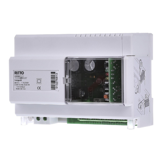
Installation: Assembly, connection and start-up TwinBus power supply unit and accessories 2.7.1 TwinBus power supply unit 1 7573 Assembly Remove the TwinBus device and the supplied components from the packaging. 9 3- 147- " 9 4- 538- Cut off the cover for connecting to additional devices. - Page 100 Installation: Assembly, connection and start-up Connection 7573 a2 b a3 b RiTT O 4760 S00 3-2 * Provide line safety switch Starting up How to program commands into the power supply unit is described during the start-up of the coding module 1 4764 and the access module 1 4768.
-
Page 101: Twinbus Floor Control Unit 1 4585
Note: Thermal fuses Instead of conventional melting fuses the TwinBus power supply unit 1 7573 has two electronic fuses that interrupt the respective power circuit if an overload occurs. If one of these fuses activates, the associated voltage indicator LED goes off. Proceed as follows to switch on again: Switch mains voltage off and leave off for approximately 1 minute. - Page 102 Installation: Assembly, connection and start-up Connection 7573 b a2 b a3 b 4585 TV NV Vb Va Vb a RiTT O 4760 S00 2-2 Circuit diagram::floor line (ET) to main bus (a). See also circuit diagram "multi-family and office building with separate door stations" on page Starting up Operating elements 1.
-
Page 103: Twinbus Switching Device 1 4981
1 4585 must first be switched to programming mode, then the indoor telephones and indoor video stations must be programmed. 2.7.3 TwinBus switching device 1 4981 Assembly Remove the TwinBus device and the supplied components from the packaging. " 128- 129- * Cut off the cover for connecting to additional devices. - Page 104 The switching device switches on for as long as the connected button is pressed. Note: No TwinBus control is possible in this operating mode. Time relay (long Each switching command switches the switching device on for the long time) with time that has been set;...
- Page 105 If 10 bell buttons have already been programmed, the memory of the device is full. If necessary, delete all settings and reprogram all required switching commands. 3) A maximum of 10 switching commands can be set. A switching command is triggered by a TwinBus unit (e. g. switch light on with light button , control button internal call button...
-
Page 106: Twinbus Door Selector Switch 1 4982
4) Operating mode switch must not be set to “0” or “7”. 2.7.4 TwinBus door selector switch 1 4982 Assembly Remove the TwinBus device and the supplied components from the packaging. " 368- 239- * Cut off the cover for connecting to additional devices. - Page 107 Installation: Assembly, connection and start-up Connection 1 7573 11 a1 b 1 498 A A 1 B B 1 Va Vb Va Vb Va Vb RiTT O 1 4760 1 4751 RiTT O 1 4760 1 4751 S00 9-3 * Please note the red mark – see “Bus connections in the door station” on page ** Open: without busy function Bridged: Busy function Circuit diagram: two door stations.
-
Page 108: Twinbus Area Coupler 1 4213
An existing link between a door station and the system is maintained. The bell button cannot be operated from another door station for approximately 25 seconds whilst the link exists. 2.7.5 TwinBus area coupler 1 4213 Assembly Remove the TwinBus device and the supplied components from the packaging. Please also follow the provided operating instructions. " 368- 36 - * Cut off the cover for connecting to additional devices. - Page 109 * Please note the red mark – see “Bus connections in the door station” on page Circuit diagram: area coupler with line coupler. Starting up The central RITTO customer center will assist you in starting up (Tel: +49 (0) 2773 / 812-111). Operating elements 1. LED TwinBus false polarity 2.
-
Page 110: Twinbus Line Coupler 1 4214
See circuit diagram "Area coupler with line coupler" on page 109. Starting up The central RITTO customer center will assist you in starting up (Tel: +49 (0) 2773 / 812-222). The documents that are required are enclosed with area coupler 1 4213. Operating elements 1. -
Page 111: Video Power Supply Unit 1 4874
Installation: Assembly, connection and start-up 2.7.7 Video power supply unit 1 4874 Assembly Remove the unit and the supplied components from the packaging. 269- 27 - Connection 1 7857 1 7855 1 7835 1 7845 1 4874 0120-1 Note: Thermal fuses The video power supply unit 1 4874 has an electronic fuse that interrupts the power circuit if an overload occurs rather than conventional melting fuses. -
Page 112: Twinbus Video Floor Distributor 1 4812
Set the output voltage using the changeover switch (1). Illuminated LED (2) indicates a voltage of 18 V, and LED (3) indicates 24 V. 2.7.8 TwinBus video floor distributor 1 4812 Assembly Remove the TwinBus device and the supplied components from the packaging. " N " N "... -
Page 113: Twinbus Video Line Distributor 1 4813
0031-2 Starting up No start-up is required. 2.7.9 TwinBus video line distributor 1 4813 Assembly Remove the TwinBus device and the supplied components from the packaging. " 245- 236- * Cut off the cover for connecting to additional devices 1. Coaxial input 2. -
Page 114: Twinbus Line Switch 1 4814
DIP switch (2) can be used to adapt the signal of the coaxial input. 2.7.10 TwinBus line switch 1 4814 Assembly Remove the TwinBus device and the supplied components from the packaging. " 238- 368- * Cut off the cover for connecting to additional devices. - Page 115 Installation: Assembly, connection and start-up Connection Power can also be supplied via the system bus or the mains transformer 1 6477. 1 4814 Va Vb 0027-2 Circuit diagram: line switch connection. 1 4814 Va Vb 1 4814 Va Vb 0028-2 Circuit diagram: Cascading with 2 line switches.
- Page 116 Installation: Assembly, connection and start-up Starting up Line switch 1 4814 and the indoor video stations connected to it are programmed to each other during start-up. All occupied video busses (1 to 6) at the line switch must be selected in sequence and the indoor video stations connected to this videobus must be programmed as described for the relevant indoor video station in order to do this.
-
Page 117: Twinbus Camera Selector Switch 1 4915
Installation: Assembly, connection and start-up 2.7.11 TwinBus camera selector switch 1 4915 Assembly Remove the TwinBus device and the supplied components from the packaging. " 237- 248- * Cut off the cover for connecting to additional devices Connections a, b... - Page 118 Installation: Assembly, connection and start-up Starting up The number of connected cameras must be set using the camera selector switch (DIP switch). The camera selector switch can be operated in different operating modes. The desired operating mode must be set using the operating mode switch (1).
- Page 119 Installation: Assembly, connection and start-up Adjusting the operating mode Function Activity Result Open plexiglass cover on camera selector switch Time setting for operating mode 3 Select operating APEM s mode "0" APEM s APEM s LD flashes * Press "Z" Number of cameras APEM s APEM s...
-
Page 120: Power Supply Unit 1 6371
Installation: Assembly, connection and start-up 2.7.12 Power supply unit 1 6371 Assembly Remove the unit and the supplied components from the packaging. 147- " 9 4- 525- * Cut off the cover for connecting to additional devices. Connections L, N Connection to the mains power Operating voltage 11 V AC Operating voltage 11 V AC... - Page 121 Installation: Assembly, connection and start-up Option: Tone generator The tone generator 1 6990 provides a signal tone at terminals – and 19. 526- Connection 1 371 +12V +24V Tonruf AC 11 V * Provide line safety switch Starting up No start-up is required. 1.
-
Page 122: Mains Transformer 1 6476
Installation: Assembly, connection and start-up 2.7.13 Mains transformer 1 6476 Assembly Remove the unit and the supplied components from the packaging. " - 8 V 3 0 V 5 0 H 471- 472- 473- Connection 6476 S0004-2 Starting up No start-up is required. Note: The mains transformer 1 6476 has an electronic fuse that interrupts the power circuit if an overload occurs rather than conventional melting fuses. -
Page 123: Mains Transformer 1 6477
Installation: Assembly, connection and start-up 2.7.14 Mains transformer 1 6477 Assembly Remove the unit and the supplied components from the packaging. " ! 8 " & 8 267- 268- 441- Connection 6477 S0032-2 Starting up No start-up is required. Note: The mains transformer 1 6477 has an electronic fuse that interrupts the power circuit if an overload occurs rather than conventional melting fuses. -
Page 124: Twinbus Door Handsfree Amplifier 1 4680
Installation: Assembly, connection and start-up 2.7.15 TwinBus door handsfree amplifier 1 4680 Assembly Remove the TwinBus device and the supplied components from the packaging. " 515- 462- * Cut off the cover for connecting to additional devices. Connections TÖ, TÖ... - Page 125 8. Potentiometer, volume setting to door station 519- Bell button setting The door hands-free amplifier must be set as follows to signal the TwinBus door call on the telecommunication system. Note: Before performing the setting procedure it is advisable to delete any previously set call numbers –...
-
Page 126: Twinbus Telecommunication Adapter A/B 1 4685
A telephone with MFV extended area calls for the telecommunication system is used for installation. Switching commands are set up in the TwinBus switching device 1 4981 – see page... - Page 127 Installation: Assembly, connection and start-up Assembly Remove the TwinBus device and the supplied components from the packaging. For more information, please read the provided instructions. " 4 8- 462- * Cut off the cover for connecting to additional devices. Connections...
- Page 128 Installation: Assembly, connection and start-up Starting up Operating elements 1. LED, speech connection 2. LED, device busy 3. LED, door opening relay 4. Potentiometer, volume setting from door station 5. Potentiometer, volume setting to door station " 4 9- Function Activity Result Dial the telephone no.
- Page 129 If not call number is specified, memory location ii is deleted. 11 ii Select TwinBus telegram for memory location ii. A speech connection to the door is set up. After the speech connection has been terminated using key a ten second time window opens.
- Page 130 Dial 00 tone location 00 Dial 40 dial speech connection Dial 11 RiTT O to door station Set TwinBus telegram Dial 00 established dial speech connection is disconnected Press button within Door and floor calls are stored in call RiTT O...
- Page 131 Installation: Assembly, connection and start-up Example 1: The telecommunication adapter dials a subscriber of the telecommunications system. Because the ringing tone from the fixed-line network has a faster cycle than usual, the software of the telecommunication adapter recognises the ringing tone as the busy tone and the connection will be terminated again. The user receives the impression that the call time is set too short.
-
Page 132: Door Stations
Installation: Assembly, connection and start-up Door stations 2.8.1 Modular Portier door station Assembly Remove the TwinBus device and the supplied components from the packaging. Frame installation " " N " N " N 346-1 Module installation O b e 351-1... - Page 133 Installation: Assembly, connection and start-up Module removal 353-1 352-1 Remove unlocked module. Remove module carrier. Deploy camera module anti-theft device The provided anti-theft device can be used to prevent the modules from being stolen. 35 - The lowest module must be installed without an anti-theft device in order to be able to remove the other modules when required.
-
Page 134: Compact Door Station Entravox 1 8401 - 1 8404
Installation: Assembly, connection and start-up 2.8.2 Compact door station Entravox 1 8401 - 1 8404 Assembly Remove the unit and the supplied components from the packaging. 547- 548- " 549- 55 - Connection 1 7573 1 2 3 4 b a1 b a2 b a3 1 8401 ...1 8404 0091-2... -
Page 135: Compact Door Station Entravox Video 1 8431 - 1 8432
Installation: Assembly, connection and start-up Operating elements 551- 1. Microphone volume setting 2. Speech volume setting Starting up Function Activity Result Open the cover on the door station Adjust potentiometer Adjusting the listening Volume has been adjusted volume Adjusting the intercom Adjust potentiometer Volume has been adjusted volume... - Page 136 Installation: Assembly, connection and start-up 587- 588- " 589- 59 - Connection 1 7573 1 2 3 4 b a1 b a2 b a3 1 6477 1 8431 Va Vb ...1 8432 0096-2 * including illumination...
- Page 137 Installation: Assembly, connection and start-up Operating elements 591- 1. Microphone volume setting 2. Speech volume setting Starting up Function Activity Result Open the cover on the door station Adjust potentiometer Adjusting the listening Volume has been adjusted volume Adjusting the intercom Adjust potentiometer Volume has been adjusted volume...
-
Page 138: Verrano Glass Door Station 1 8301-1 8304, 1 8311-1 8314, 1 8321-1 8324 And 1 8331-1 8334
Installation: Assembly, connection and start-up 2.8.4 Verrano glass door station 1 8301–1 8304, 1 8311–1 8314, 1 8321–1 8324 and 1 8331–1 8334 Assembly Note: Observe the installation height for systems with a video camera. a. 1,6 m 00615-0 Remove the unit and the supplied components from the packaging. Frame installation Plaster the flush-mounted frame after bending the two wall anchors at the left- and right-hand side. - Page 139 Installation: Assembly, connection and start-up 617- 618- " N 62 - 619- After completing the installation, set the Verrano glass door station in the installation box. 626- 621- 629- Fasten the glass door station in the installation box with the screw.
- Page 140 Installation: Assembly, connection and start-up Connection 1 7573 a3 b 11 1 8301 ...1 830 S0097-1 Circuit diagram: Verrano glass door station 1 7573 a3 b 11 1 6 77 1 8311 ...1 831 S0098-1 Circuit diagram: Verrano video glass door station Note: A mains transformer 1 6476 must be provided to supply an LED illuminated ring with power.
-
Page 141: Twinbus Built-In Loudspeaker 1 4921
Adjusting the Adjusting the listening Volume has been adjusted potentiometer volume Adjusting the Adjusting the intercom potentiometer Volume has been adjusted volume 2.8.5 TwinBus built-in loudspeaker 1 4921 Assembly Remove the TwinBus device and the supplied components from the packaging. 274-... - Page 142 Installation: Assembly, connection and start-up Operating elements 1. Apartment-to-door volume setting 2. Door-to-apartment speech volume setting 3. Bell button connection 4. Door bus connection / 4-wire " 275-1 Connection 1 7573 1 2 3 4 21 a1 a3 b 1 4921 K2 K3 K4 K5 K6 K7 K8 K9 11 12 KL12...
-
Page 143: Twinbus Extension Unit 1 4923
2.8.6 TwinBus extension unit 1 4923 Assembly Remove the TwinBus device and the supplied components from the packaging. Please note the length of the bus connector during installation to avoid problems when connecting the expansion unit to the built-in loudspeaker. -
Page 144: Staircase Door Station 1 8201
Installation: Assembly, connection and start-up 2.8.7 Staircase door station 1 8201 Assembly Remove the TwinBus device and the supplied components from the packaging. Note: the speech quality depends on the installation of the device. Install the staircase door station at the operator's eye level. - Page 145 Installation: Assembly, connection and start-up 7 7- Concealed and cavity wall installation Plaster in a 1 7322 flush-mounted frame or attach it using the enclosed cavity wall clamps. 1. Cavity wall clamp 2. Fastening screws for cavity wall clamps 3. Plastering protection h: 174 mm b: 122 mm 35 mm...
- Page 146 Connect screening on incoming and outgoing lines. Connect all unused wires as screen for YR lines. Starting up Prior to start-up, the bell button of the staircase door station must be assigned to a TwinBus intercom unit. For the exact procedure, please refer to the "Start-up" section of the TwinBus intercom unit operating manual.
- Page 147 Installation: Assembly, connection and start-up System malfunctions To prevent the door intercom system from malfunctioning, follow the specified sequence when Caution! programming the bell buttons. 1. Program the bell button of the main entrance door. 2. Program the bell button of the staircase door station. 3.
- Page 148 Installation: Assembly, connection and start-up Fill labelling field 725- Remove light button If a customer-installed light control button is used, you can remove the light button on the staircase door station and replace it with a dummy button. 721-...
-
Page 149: Built-In Colour Camera 1 4883
80 81 Va Vb 80 81 Va Vb S0074-3 A Connection to TwinBus video line and feed from mains transformer 1 6477. B Connection to 75 Ω coaxial video line and feed from mains transformer 1 6477. Starting up No start-up is required. -
Page 150: Colour Video Camera 1 7652
AC 12 V screen 1 7652 output 75 Ω yellow green yellow S0044-2 A Connection to coaxial line B Connection to TwinBus video line Insulate the green wire (connection A). Insulate the screening (connection B) Starting up No start-up is required. -
Page 151: Coding Module 1 4764
Installation: Assembly, connection and start-up 2.8.10 Coding module 1 4764 Assembly Coding module 1 4764 is installed in the RITTO Portier door station – see page Connection 1 4764 a b X Y " & 1 4765 0060-2 * Please note the red mark – see “Bus connections in the door station” on page Circuit diagram: coding module and display module connection via system bus. -
Page 152: Access Module 1 4768
The number for the residential unit is entered at the coding module during start-up instead of pressing the doorbell. 2.8.11 Access module 1 4768 Assembly The access module 1 4768 is installed in the RITTO Portier door station – see page... - Page 153 Installation: Assembly, connection and start-up Connection 1 7573 1 2 3 4 a1 b a2 b a3 b 1 6477 1 4768 0063-2 Circuit diagram:access module connection as standalone unit. Starting up The two-part 7-segment display displays the following information: 1.
- Page 154 Installation: Assembly, connection and start-up Activity Result Hold master card up in front of the access the desired memory location is displayed module until Remove master card Memory location no. illuminates for 3 s and starts flashing for 5 s Identity card is blocked, hold the master card up in front of the memory location is counted up...
- Page 155 LD 1 goes out access module LD 3 illuminates Press and hold "P" until LD 3 goes out Set the switching command at the switching device 1 4981, refer to "TwinBus switching device 1 4981" page...
- Page 156 Installation: Assembly, connection and start-up...
-
Page 157: Operation
Operation Operation The operation of a TwinBus system depends on the configuration of the system and the TwinBus devices that are used. Please notify the end user how the system works and instruct the user how to operate the system. -
Page 158: Door Intercom Systems Without Internal Voice Communication
Automatic door opening (Portamat) RiTT O Handsfree voice connection with door station Door intercom systems without internal voice communication See TwinBus units Door intercom systems with internal voice communication See TwinBus units Video-door intercom systems without internal voice communication See TwinBus units... - Page 159 Operation Indoor telephones, indoor video stations and intercom units 3.5.1 TwinBus indoor telephone 1 7630 Function Activity Result Call tone Trigger call signal RiTT O flashes sounds (ring) Operate door press. Door opener opener switches Switch on/off press briefly call signal...
-
Page 160: Twinbus Comfort Indoor Telephone 1 7650
Operation 3.5.2 TwinBus comfort indoor telephone 1 7650 Function Activity Result Trigger call signal RiTT O Call tone flashes (ring) sounds Door opener switches Operate door press. opener set up internal Call tone Dial sounds illuminate voice subscriber connection Switch on/off call... - Page 161 Operation Function Activity Result Pick up receiver > 5 s Press own LED flashes 1x Activate call memory internal no. for >5 s Pick up receiver > 5 s Press own LED flashes 2x Disable call memory internal no. for >5 s missed calls are Pick up receiver...
-
Page 162: Twinbus Colour Indoor Video Station 1 7857
Operation 3.5.3 TwinBus colour indoor video station 1 7857 Function Activity Result Trigger call signal RiTT O Call tone flashes (ring) sounds Operate press. Door opener switches door opener Switch on/off press briefly call signal illuminates (call switch-off) press briefly... -
Page 163: Twinbus Comfort Indoor Video Station 1 7855
Operation 3.5.4 TwinBus comfort indoor video station 1 7855 Switch on operating menu Button Result The display shows the operating menu. Menu control Button Function Control keys Use the control keys to move within the menu structure. The selected menu item is highlighted by the symbol ">"... - Page 164 Operation Menu item "Video" Video Brightness Contrast Colour Video switch-on time Back Menu item Setting options brightness Scroll bars can be used to set 22 different shades of brightness. contrast Scroll bars can be used to set 22 different shades of contrast. Colour Scroll bars can be used to set 22 different shades of colour.
- Page 165 Call tone sounds Switch additional Pick up Switching device press briefly function (e.g. receiver switches staircase light) press Video image switched RiTTO control key RiTTO RiTTO Switch on video press Video image image manually switched off control key press. Special function 1) Optionally with switching device 1 4981, e.
-
Page 166: Twinbus Handsfree Video Intercom Unit 7835
Operation 3.5.5 TwinBus handsfree video intercom unit 7835 Note: The handsfree video intercom unit is operated with the keys and controlled with the on-display menu. Switch on operating menu Button Result The display shows the operating menu. Menu control Button... - Page 167 Operation Video Contrast Colour Video switch-on time Back Menu item Setting options brightness Scroll bars can be used to set 22 different shades of brightness. contrast Scroll bars can be used to set 22 different shades of contrast. Colour Scroll bars can be used to set 22 different shades of colour. Video switch-on The video switch-on duration can be adjusted in 30 s increments between 30 s and 180 s.
- Page 168 Operation Menu item "Camera" Camera Switch camera Select camera Back Menu item Setting options 1) 2) Switch camera Control camera Select camera You can switch between a maximum of 6 cameras Submenu item "Switch camera" Menu item Setting options <…> Adjust the viewing area of the camera Camera: left/right Switch between 2 recording facilities...
- Page 169 Switch on video press Video image switched image manually RiTTO control key RiTTO RiTTO press Video image switched control key press. Special function 1) Best voice quality at a distance of an arm's length.
-
Page 170: Twinbus Comfort Handsfree Video Intercom Unit 1 7845
Operation 3.5.6 TwinBus comfort handsfree video intercom unit 1 7845 Switch on operating menu Button Result The display shows the operating menu. Menu control Button Function Control keys Use the control keys to move within the menu structure. The selected menu item is highlighted by the symbol ">"... - Page 171 Operation Menu item "Video" Video Brightness Contrast Colour Video switch-on time Back Menu item Setting options brightness Scroll bars can be used to set 22 different shades of brightness. contrast Scroll bars can be used to set 22 different shades of contrast. Colour Scroll bars can be used to set 22 different shades of colour.
- Page 172 Switch additional Switching device function (e.g. switches press and press. staircase light) hold Switch on video press Video image switched image manually RiTTO control key RiTTO RiTTO press Video image switched control key Label directory Ð 8 press. Special functions 1) Best voice quality at a distance of an arm's length.
-
Page 173: Twinbus Compact Intercom Unit 1 7132
Operation 3.5.7 TwinBus compact intercom unit 1 7132 Function Activity Result Trigger call signal Call tone RiTT O flashes (ring) sounds press. Door opener switches Operate door opener Establish voice Voice connection press and hold iTTO connection to door active for... -
Page 174: Twinbus Handsfree Intercom Unit 1 7230
Operation 3.5.8 TwinBus handsfree intercom unit 1 7230 Function Activity Result Trigger call signal Call tone RiTT O flashes (ring) sounds Door opener Operate door press. switches opener illuminates Establish voice press. iTTO connection Voice connection active for 1 min... -
Page 175: Twinbus Signalling Device 1 7930
Operation 3.5.9 TwinBus signalling device 1 7930 Function Activity Result Trigger call signal RiTT O Call tone (ring) flashes sounds Operate door press. Door opener opener switches Switch on/off press briefly illuminates call signal (call switch-off) Call tone sounds press briefly... -
Page 176: Twinbus Radio Signalling Device 1 7950
Operation 3.5.10 TwinBus radio signalling device 1 7950 Note: after you answered the door call at the indoor intercom unit, call signalling will not be interrupted. The call tone will be played back until the time you set has elapsed. -
Page 177: Twinbus Intercom Station 1 7133, 1 7134, 1 7135, 1 7136
Operation 3.5.11 TwinBus intercom station 1 7133, 1 7134, 1 7135, 1 7136 Function Activity Result Call tone sounds Trigger call signal RiTT O (ring) Operate door press. Door opener opener switches Establish voice press and hold Voice connection to... -
Page 178: Accessories For Indoor Telephones, Indoor Video Stations And Intercom Units
No operation is required. 3.6.7 TwinBus desktop console Video 1 7313 No operation is required. 3.6.8 TwinBus flush-mounted frame 1 7320, 1 7321, 1 7322 No operation is required. 3.6.9 TwinBus coaxial connection adapter 1 4811 No operation is required. -
Page 179: Twinbus Power Supply Unit And Accessories
3.7.10 TwinBus line switch 1 4814 No operation is required. 3.7.11 TwinBus camera selector switch 1 4915 Operation takes place via the TwinBus indoor video station. 3.7.12 Power supply unit 1 6371 No operation is required. 3.7.13 Mains transformer 1 6476 No operation is required. -
Page 180: Twinbus Telecommunication Adapter A/B 1 4685
Operation 3.7.16 TwinBus telecommunication adapter a/b 1 4685 Function Activity Result Trigger call signal RiTT O Call tone sounds (ring) Carry out door intercom Special signal sounds Pick up receiver conversation after ringing Connection press any numeric key iTTO 0...9... -
Page 181: Door Stations
3.8.4 Verrano glass door station When a bell button is pressed, a signal tone can be heard and the nameplate next to the bell button illuminates brighter. 3.8.5 TwinBus built-in loudspeaker 1 4921 No operation is required. 3.8.6 TwinBus extension unit 1 4923... -
Page 182: Staircase Door Station 1 8201
1) If a call is already in progress on the TwinBus, this call will be disconnected after 10 seconds by call waiting. Ongoing conversations will be disconnected immediately on devices with older power supply units. 2) Optionally with switching device 1 4981, e. g. switch light. -
Page 183: Service Speech
15 V DC or 30 V DC with door communication 24 V DC 11 V AC TwinBus indoor telephone and indoor video station Clamp Target voltage 20 V DC to 28 V DC 20 V DC to 28 V DC AC 16 V or DC 18 V <... -
Page 184: Service Indicators
Service speech Service indicators TwinBus power supply unit 1 7573 & 8 7- Indicator Meaning LED 1 (yellow) flashes The door opener operating time is set (LED flashes every second when door opening time is being set). LED 2 (red) is lit Indicates transmission of bus commands, e.g.:... -
Page 185: Troubleshooting Table
TwinBus power supply unit 1 7573. No call signal from the Disconnect the three Thermal fuse of TwinBus De-energize power supply modular door station to all bus lines from the power power supply unit 1 7573 unit 1 7573 –... - Page 186 At power supply unit 1 7573 Short circuit Remedy short circuit. loudspeaker 1 4921 to all , the target voltage of 11 V Thermal fuse of TwinBus De-energize power supply intercom units. AC cannot be measured power supply unit 1 7573 unit 1 7573 –...
- Page 187 Service speech Fault Measuring point/test Cause Remedy No call signal for The door is opened by the Automatic door opener Deactivate automatic door indoor telephones 1 7650 pressing of the doorbell. activated. opener. Refer to Page: for indoor telephone indoor video station 1 7650;...
- Page 188 Image fault at indoor video Optical inspection. Connections Va and Vb of Switch round connections station/handsfree video the TwinBus video line have Va and Vb of the TwinBus intercom unit (Negative been switched. video line. image). Image at indoor video Voltage between terminals Supply voltage too low.
- Page 189 Service speech Fault Measuring point/test Cause Remedy Camera module 1 4787 or Optical inspection. Bus connector to camera Check bus connection in 1 4788 not switching module missing. door station (observe red over. mark).
-
Page 190: Index
Index Index Access module ............................152 Adjustment protection ................... 36, 43, 50, 53, 63, 70, 100 Anti-theft device ............................133 Area coupler ............................. 108, 109 Article numbers ............................. 8 Assigning the doorbell ..........................43 Assigning the internal call number ......................45 Automatic door opening (Portamat) ...................... - Page 191 Index Flush-mounting radio transmitter ........................ 98 Frame installation ............................. 132 Fuse, electronic ..........................101, 111 Identity card .............................. 153 indoor telephone ............................33 Intercom station ............................ 89, 90 Intercom unit without receiver ........................76 Interface 123D-12 ............................. 124 Internal communication ..........................19 Line coupler ..............................
- Page 192 Index Troubleshooting ............................185 TwinBus power supply unit 1 7573 ..................10, 99, 183, 184 Verrano ..............................138 Verrano glass door station ........................138 Video camera ............................150 Video handsfree intercom unit, colour .................... 46, 52, 58 Video indoor station start-up ........................50 Video line distributor ..........................
- Page 193 Notes...
- Page 194 Notes...
- Page 195 Notes...
- Page 196 Notes...
- Page 197 RITTO GmbH & Co. KG Rodenbacher Straße 15 D-35708 Haiger/Germany Phone +49(0)2773/812-0 +49(0)2773/812-999 www.ritto.de • info@ritto.de...
Need help?
Do you have a question about the TWINBUS and is the answer not in the manual?
Questions and answers