Advertisement
Quick Links
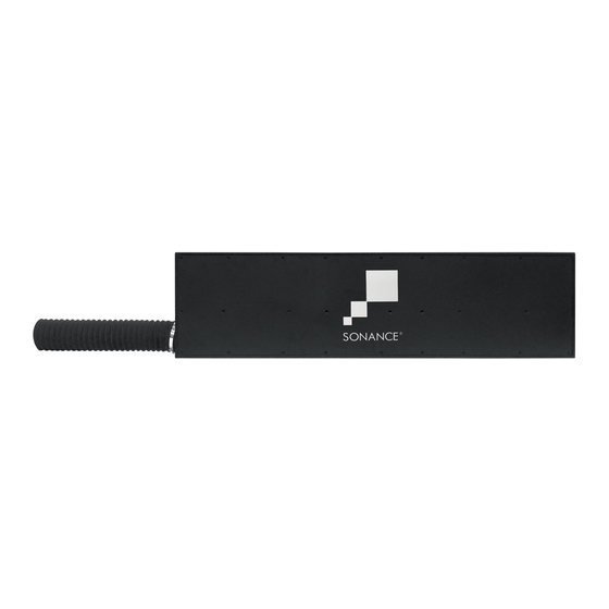
BANDPASS SUBWOOFER THINLINE (AS)
BPS6 TL QUICKSTART GUIDE FOR USE WITH
ARCHITECTURAL SERIES BANDPASS CONNECTORS
Box Contents
(1) Quickstart Guide
(1) Bandpass Subwoofer with port tube
(1) Cardboard mounting template
Port Tube
15" (381mm)
Architectural Series
mounting platform
Figure 1
Determine the location of the mounting platform
and subwoofer. Ensure there is adequate space to
accommodate the subwoofer and port tube within the
2 x 4 stud bay or joist, allowing 15" from the front edge
of the BPS6 TL to the center of connector. (See Figure 1).
NOTE: IF IT IS NOT POSSIBLE TO LOCATE THE BPS6 TL SUBWOOFER
15" AWAY FROM THE 90 DEGREE CONNECTOR OF THE MOUNTING
PLATFORM, EXTRA HOSE MATERIAL (UP TO 3") MAY BE REMOVED.
WHILE IT IS OKAY TO SHORTEN THE HOSE, NEVER EXTEND THE
HOSE LENGTH.
Figure 2
Place the subwoofer mounting template on the side of a
2 x 4 stud or joist and drill four 1/4" (6mm) holes through
the stud at the locations shown on the mounting template.
(See Figure 2).
1
BPS6 TL
2
Template
MOUNTING SCREWS & WASHERS:
(4) 5/16" x 3" lag screws
(4) 5/16" washers
NOTE: DRILLING FROM THE INSIDE OF THE STUD BAY IS
RECOMMENDED TO ENSURE THAT THE HOLE LOCATIONS
MATCH THE SUBWOOFER SCREW LOCATIONS. (SEE FIGURE 2)
NOTE: BE SURE THAT THE SUBWOOFER TEMPLATE IS FLUSH
WITH THE EDGE OF THE STUD OR SLIGHTLY RECESSED.
Figure 3
Hold the side of the BPS6 TL Subwoofer with the rubber
damping pad up against the side of the stud or joist and
install the four lag screws and washers to secure the
BPS6 TL Subwoofer in place. (See Figure 3).
Figure 4
Prepare to attach the mounting platform to the stud
or joist. Position the platform with the 90 degree
connector pointed in the direction of the BPS6 TL
port tube. (See Figure 4).
3
4
Advertisement

Related Manuals for Sonance BPS6 TL


Summary of Contents for Sonance BPS6 TL
-
Page 1: Box Contents
2 x 4 stud bay or joist, allowing 15” from the front edge of the BPS6 TL to the center of connector. (See Figure 1). Figure 3 NOTE: IF IT IS NOT POSSIBLE TO LOCATE THE BPS6 TL SUBWOOFER Hold the side of the BPS6 TL Subwoofer with the rubber 15”... - Page 2 For the latest Sonance product specification information visit our website: www.sonance.com 33-7939 10.24.17 SONANCE • 991 Calle Amanecer • San Clemente, CA 92673 USA • PHONE: (949) 492-7777 • FAX: (949) 361-5151 • Technical Support: (949) 492-7777...
Need help?
Do you have a question about the BPS6 TL and is the answer not in the manual?
Questions and answers