Table of Contents
Advertisement
Advertisement
Table of Contents

Subscribe to Our Youtube Channel
Related Manuals for Xprinter R330H


Summary of Contents for Xprinter R330H
- Page 1 Service Manual for R330H Desktop POS Printer...
- Page 2 Record of Changes Version Date Content of Change Made by Reviewed Approved...
-
Page 3: Table Of Contents
Table of Contents Notes for Maintenance ..........................5 1. Characteristics of the Printer ......................... 6 1.1 Overview............................6 1.2 Main Characteristics.......................... 6 1.3 Technical Parameters ........................7 Appearance and Components ........................2.1 Outer Appearance of the Product ...................... - Page 4 Guide on Trouble-shooting..........................19 5.1 Power Supply............................19 Printing..............................19 Paper Feed.............................. 20 Cash drawer ............................20 Indicator/Buzzer............................21 Communication............................21 Paper Cutting............................22 Dismantlement and Assembly of Main Parts ....................23 Dismantlement of the Printer........................23 6.1.1 Dismantlement of the base of the printer..................23 6.1.2 Dismantlement of front cover of the printer...................
-
Page 5: Notes For Maintenance
Notes for Maintenance Prior to operation and use of the printer, read the following notes carefully: 1. Safety warning Warning: The printing head is a heating part, do not touch it or parts neighboring it while printing or when printing is just over. Warning: Do not touch the printing head and the connecting parts lest the printing head be damaged by static electricity. -
Page 6: Characteristics Of The Printer
1、Characteristics of the Printer 1.1 Overview This printer is a thermal note printer equipped with automatic cutter, it has the characteristics of high printing quality, high speed and high stability and it can be applied in commercial POS system and catering industry and so on widely where on-site real-time printing of notes is required. -
Page 7: Technical Parameters
1.3 Technical Parameters Model R330H Color Black Printing mode Direct row-type thermal printing Printing speed 300mm/s Width of paper roll 58mm(57.5±0.5mm),80mm(79.5±0.5mm),83mm(82.5±0.5mm) Paper roll ID MinФ13mm, OD Max Ф83mm Thickness of paper 0.06-0.08mm Printing width 52/72/80±0.5mm (can be adjusted through command) Paper-out mode "Front paper out"... - Page 8 (Iran), (WPC1252), PC866(Cyrillic#2), PC852(Latin2), (PC858), (IranII), (Latvian), (Arabic), (PT1511251) Reliability Service life of the cartridge is 100 kilometers and that of the cutter is 1 million times Paper-cutting mode Semi-cutting Paper detection Photoelectric sensor Black-label positioning Supported Input buffer 64Kbytes NV Flash 256Kbytes Voltage input of adaptor...
-
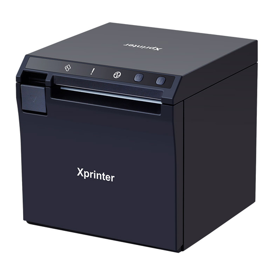
Page 9: Appearance And Components
2、Appearance and Components 2.1 Appearance of the Product 1--Cutter and moving knife set 2--Rack of cartridge 3--Flip cover 4--Partition board 5--Base 6--Front cover 7--FEED Paper feed key 8--POWER Power key 9--POWER Power indicator 10--ERROR Status indicator 11--PAPER Paper lacking indicator 12--Fixed knife set 13--Rubber roller 14--Gear of rubber roller... -
Page 10: Connecting Diagram For Components Of Control Panel
2.2 Connecting Diagram for Components of the Control Panel The printer composed of main control board, printing cartridge, cutter, keys and buttons is connected to the mainboard via connectors or pinboard, and the following is the connecting diagram of USB+network interface and USB+serial interface control panel assembly: Fig 2.2.1 Connection Diagram of USB+ Network Interface Control Panel Fig 2.2.2 Position Diagram for USB+ Network Interface Control Panel... - Page 11 Fig 2.2.3 Connection Diagram for USB+Serial Interface Control Panel Fig 2.2.4 Position Diagram for USB+ Serial Interface Control Panel...
-
Page 12: Interfaces Of The Printer
2.3 Interfaces of the Printer 2.3.1 Power interface SIGNAL NAME +24V SHELL 2.3.2 Interface of Cash drawer Cashier-box control: 6-line RJ-11 socket, output DC 24V/1A power signals to drive actions of Cash drawer. SIGNAL NAME FGND Drawer 1 CASH Drawer 2 654321... -
Page 13: Usb Interface
2.3.3 USB interface SIGNAL NAME VBUS D- (DATA-) D+ (DATA+) 2.3.4 Serial interface SIGNAL NAME... -
Page 14: Ethernet Interface
2.3.5 Network interface SIGNAL NAME GREEN+ GREEN - YELLOW+ YELLOW-... -
Page 15: Keys, Buttons, Indicators And Functions
3、Keys, Buttons, Indicators and Functions 3.1 Paper-feed key ( When the printer does not alarm, press the key to feed paper, and hold it to feed paper continuously. 3.2 Power key ( Press this key 1-2 seconds to turn on/off the printer. 3.3 Power indicator ( The indicator light is blue in color. -
Page 16: Description Of The Printer's Status
3.6 Description of the printer's status Status of errors Including overheating of the printing head, cover opening, paper lacking, cutter jam and paper jam, etc. Standby status No error, no printing, no paper feed, waiting for printing task of the printer. Printing status The process from start to end of printing the contents after the printing contents are received. -
Page 17: Connecting To Cable
Cautions: 1) Use the dedicated power adaptor or an equivalent product; 2) While inserting or pulling the plug of the power adaptor, be sure to hold the connector's housing of the plug, and avoid pulling the cable with force; 3) Avoid dragging the cable of the power adaptor, or the cable may be damaged and a fire or electrical shock may be caused;... - Page 18 1.Card slot 1 2. Card slot 2 3. Partition board Choose a suitable position according to the width of the paper, and insert the partition board downward vertically (Note: the partition board is mounted at the position of card slot 1 by default) Notes: The partition board is in card slot 1: The paper roll with width of 80mm(79.5±0.5mm) is supported.
-
Page 19: Guide On Trouble-Shooting
5、Guide on Trouble-shooting In case any fault occurs for the printer, it can be handled in accordance with this chapter, If the fault cannot be solved in this way, contact the dealer or the manufacturer. 5.1 Power Supply Fault Possible cause Solution AC/DC power adaptor is not Connect the power adaptor again... -
Page 20: Paper Feed
5.3 Paper Feed Fault Possible cause Solution Remove the jammed paper and load the printing The printer is jammed with paper paper as per the requirement in the manual The gear is damaged Change the gear Paper does not enter or paper feed The mainboard is damaged Repair or change the mainboard is not normal... -
Page 21: Indicator/Buzzer
5.5 Indicator/Buzzer Fault Possible cause Solution The cable for key indicator is not Connect the cable again connected reliably The cable or connector is damaged Change the cable or connector Key or indicator does not work The key or indicator is damaged Change the key or indicator Status display circuit is damaged Change or repair the mainboard... -
Page 22: Paper Cutting
5.7 Paper Cutting Fault Possible cause Solution The blade is distorted Change the cutter The motor is burned Change the cutter Knife is jammed Scraps of paper are accumulated Clean the scraps on transmission parts Plate of driving head is over-heated Lower heating power of the driving head Paper is jammed Align edge of paper with the paper slot and put... -
Page 23: Dismantlement And Assembly Of Main Parts
6、Dismantlement and Assembly of Main Parts Cautions in operation: 1) When the printer is working normally, do not dismantle any part of the printer, nor loosen any screw of the printer; 2) While dismantling parts, check if the connecting cable is damaged or not carefully; 3) In the process of handling the printing cartridge and electronic elements, taking anti-static measures;... -
Page 24: Dismantlement Of Front Cover Of The Printer
First take off the bottom cover of the printer A. Take off L-shaped foot pads. B. Dismantle the two H3*6mm screws for fixing the base with a cross screwdriver, and then take off the base in the same direction. 6.1.2 Dismantlement of the Front Cover of the Printer Picture Illustration Dismantle the two H3*6mm screws for... - Page 25 Move downwards for 2.5mm along the direction indicated with the arrow (Caution: do not pull out the front cover directly) Take off the front cover gently. Dismantle the two CA2.2*3.5mm screws for fixing the blade with a small cross screwdriver, and then take off the blade.
-
Page 26: Dismantlement Of Flip Cover Of The Printer
Dismantle the two PB3*6mm screws for fixing the lamp panel with a cross screwdriver, and then take off the lamp panel. 6.1.3 Dismantlement of the Flip Cover of the Printer Picture Illustration Dismantle the BM2*3mm screw for fixing the cover-opening button with a small cross screwdriver, and then take off the cover-opening button. -
Page 27: Dismantlement Of The Main-Board And Interface Board Of The Printer
Take off the flip cover gently. 6.1.4 Dismantlement of the Mainboard and Pinboard of the Printer Picture Illustration Dismantle the two H3*6mm screws for fixing the mainboard with a cross screwdriver, and then take off the mainboard. - Page 28 Dismantle the two H3*6mm fixing the interface board with a cross driver. Take off the interface board. Dismantle the two H3*6mm screws for locking left/right racks with the cross driver.
-
Page 29: Assembly Of The Printer
6.2 Assembly of the Printer Assembly is just the reverse sequence of dismantlement. -
Page 30: Cleaning Of The Printer
7、Cleaning the Printer Dust, foreign matters, sticky substance or other dirt struck on the printing head or inside the printer may lower printing quality. Clean the printer with the following method. Clean the Printing Head 1) Open the flip cover of the printer, and clean the printer from its center to the two sides with a cleaning pen or a cotton stick moistened with diluted alcohol (alcohol or isopropanol). -
Page 31: Appendix: Exploded View Of The Printer
Appendix: Exploded View of the Printer 1. List of Parts of the Printer Name of material Label for keys Front cover Blade Lamp panel Mainboard Interface board Left rack Right rack Printing head Cover-opening pull rod Flip cover Bottom cover... - Page 32 Base L-shaped foot pad Ф6 round foot pad Bumper block Partition board Paper compartment Left supporting board Stationary knife Thermal slice Cover-closing board Bottom board Right supporting board Detection switch Decelerating gear Motor Upper cover for paper compartment...
- Page 33 Rubber roller Moving knife Cover-opening board Spindle...
-
Page 34: Exploded View Of The Whole Unit Of The Printer
2. Explode View of the Printer... -
Page 35: Exploded View Of The Cartridge Of The Printer
3. Explode View of Cartridge of the Printer...
Need help?
Do you have a question about the R330H and is the answer not in the manual?
Questions and answers
how to fix the upper cover
To fix the upper (flip) cover of the Xprinter R330H:
1. Move the flip cover 12mm in the direction of the arrow (do not pull it out directly).
2. Gently take off the flip cover.
3. To reattach it, reverse the steps used during removal.
Assembly is the reverse of dismantlement.
This answer is automatically generated