
Related Manuals for Gunnebo RotaSec B120S

Summary of Contents for Gunnebo RotaSec B120S
- Page 1 This Manual Refers to the RotaSec fitted with the Titan Head ......CCEC/ OM Manuals RotaSec Titan 1.5 08.2009...
- Page 2 ......CCEC/ OM Manuals RotaSec Titan 1.5 08.2009...
-
Page 3: Table Of Contents
Contents Page ............................5 ECTION NTRODUCTION General ......................5 Electrical Warnings .................... 5 Errors........................5 Proprietary Notices .................... 5 Hardware Changes..................... 5 Rotating Machinery ................... 6 Warnings, Cautions and Notes ................6 Good Practices .................... - Page 4 ............................37 ECTION NSTALLATION Unpacking ......................37 Tools Required ....................37 Site Preparation ....................37 Headroom ......................57 Conduit Routing ....................57 Cable Requirements ..................57 Cable Controls ....................57 General Details....................58 ...
-
Page 5: Section 1 Introduction
Proprietary Notices All data appearing herein is of a proprietary nature, with exclusive title to it held by Gunnebo. The possession of this Manual and the use of the information are therefore restricted only to those persons duly authorised by Gunnebo. -
Page 6: Rotating Machinery
Rotating Machinery Rotating industrial machinery may possess huge amounts of stored energy. On no account must you commence maintenance if you do not fully understand what you are doing and/or have not taken all the safety precautions normally associated with industrial electronic control systems and machines. Before starting to work on the equipment, please make yourself familiar with all the associated blocks in the system, including control loops, mechanics, drives, transducers and electrics. -
Page 7: Risk Assessment
Risk Assessment Risk assessment is graded into categories of safety, rated 1 to 8 (where 8 is the highest risk level). The following activities are covered. Rating Activity Cleaning General Installation Roof Installation Servicing Servicing General Maintenance Using Chemical Fixers Commissioning Floor Drilling Rating 1:... -
Page 8: Ce - Marking
With each unit a Declaration of Conformity is supplied. Important Notice The Gunnebo RotaSec is a security product and as such, any Children or Minors using the turnstile, MUST be supervised and accompanied by a responsible Adult. Gunnebo does not accept any liability if this Important Safety Notice is not enforced. -
Page 9: Escription
Section 2 Product Description Product Description The RotaSec is designed for use in external entrances to Administrative Centres, Industrial Complexes and Military Establishments where high quality, combined with high security full height barriers are required. An all welded steel rotor with straight arms runs in a phosphor bronze bearing at the top end and supported by a ball and cone bearing at the base. - Page 10 The following variations can be supplied by Gunnebo; however this Technical Manual provides sufficient information to cover all models. MODEL UNIT-TYPE B90S (Basic) Single Unit, open frame design without canopy B120S (Basic) Single Unit, open frame design without canopy F90S...
-
Page 11: Typical Units
Typical Units Model B90S Model F90S ......CCEC/ OM Manual RotaSec Titan 1.5 EN 08.2009... - Page 12 Model R120S Model R120DI ......CCEC/ OM Manual RotaSec Titan 1.5 EN 08.2009...
-
Page 13: Technical Details
Technical Details An all welded steel rotor with straight arms runs in a phosphor bronze bearing at the top end and supported by a ball and cone bearing at the base. On double units models are available with interlocking rotors, where space is of prime importance. Entry and Exit can be made by Card reader, Pushbutton or any other type of control device specified by the client at the time of order. - Page 14 Power Failure: In the event of an emergency or isolation of the power supply the RotaSec can be configured to Fail-Safe i.e. rotates freely or Fail-Lock i.e. locks in the HOME position. Either option is available in both or one direction. (As standard the RotaSec is configured bi-directional fail-safe unless requested otherwise) Fire Alarm:...
-
Page 15: Use
4. Pass through the RotaSec, using your hand to push the rotor. 5. The rotor will automatically lock in its new position. Note - Gunnebo recommends the fitting of a push button if free exit is required......CCEC/ OM Manual RotaSec Titan 1.5 EN... -
Page 16: Access Control Devices
The fail state is the same as that when a fire alarm signal is received. Access Control Devices Gunnebo can supply the mounting for an Access Control Device, which is specified at the initial order to meet customer requirements. Refer to Table 8.2. -
Page 17: Nformation
Rotor restoring mechanism Universal control logic Fail-safe or Fail-lock A combination of Fail-lock and Fail-safe Optional Features Gunnebo can supply the following features on request for RotaSec. Status lights (standard on S Models) Pushbuttons Card-reader mounting on bracket Stainless steel rotor Uni or Bi-directional ...... -
Page 18: Typical Layout Details
Typical Layout Details RotaSec 90 (Single Walkway) Figure 4.1 shows the general location of the main units/assemblies that comprise the single RotaSec 90. Fig 4.1 Layout details RotaSec 90 (Single Walkway) Key to illustration A - Rotor Head Mechanism B - Electrical Plate Assembly C - Logic Board D - Transformer E - Distribution Box... - Page 19 Typical Layout Details RotaSec 120 (Single Walkway) Figure 4.2 shows the general location of the main units/assemblies that comprise the single RotaSec 120. Fig 4.2 Layout details RotaSec 120 (single walkway) Key to illustration A - Rotor Head Mechanism B - Electrical Plate Assembly C - Logic Board D - Transformer E - Distribution Box...
- Page 20 Typical Layout Details RotaSec 90 (Double Walkway) Figure 4.3 shows the general location of the main units/assemblies that comprise the Double RotaSec 90. Fig 4.3 Layout details RotaSec 90 (Double Walkway) Key to illustration A - Rotor Head Mechanism (1) B - Rotor Head Mechanism (2) C - Electrical Plate Assembly D - Logic Board...
- Page 21 Typical Layout Details RotaSec 90 (Double Walkway) Figure 4.4 shows the general location of the main units/assemblies that comprise the Double RotaSec 120. Fig 4.4 Layout details RotaSec 120 (Double Walkway) Key to illustration A - Rotor Head Mechanism (1) B - Rotor Head Mechanism (2) C - Electrical Plate Assembly D - Logic Board...
- Page 22 This section gives details of the main components that comprise a RotaSec. Fig 4.5 – 90 Titan Head Mechanism Fig 4.6 – 120 Titan Head Mechanism ......CCEC/ OM Manual RotaSec Titan 1.5 EN 08.2009...
-
Page 23: Typical Titan Head Mechanism Elevation
Typical Titan Head Mechanism Elevation Figure 4.7 (Position of components vary slightly between models) Fig 4.8 – Rotor Engagement Detail Note - All Rotor variants should be inserted into the mechanism bearing as detailed above. Drives and Controls The head is mounted by means of 4 x M12 bolts through slotted holes in the chassis. The head must be mounted on bonded rubber anti-vibration mountings. -
Page 24: Restoring Force Adjustment
Restoring Force Adjustment The force exerted by the restoring spring can be adjusted to cater for a wide range of head and rotor configurations. The factors affecting the setting are: Rotor weight and diameter If the unit is damped or un-damped. General friction within the installation User preference The minimum force is always that required to rotate the unit to the next home position after the rotor... -
Page 25: Damping Adjustment
Damping Adjustment An adjustable hydraulic damper is be fitted to the head assembly. This reduces the shock and noise which can occur when the turnstile rotor reaches the home position. Figure 4.10 - Hydraulic Damper The damper should be adjusted to suit user preference and the weight diameter of the rotor. Note - There is some interaction between the damper setting and restoring force. -
Page 26: Sensor Timing And Solenoid Operation
Sensor Timing and Solenoid Operation The LCM02 microprocessor controller operates with a dc supply from the in-built PSU from 5 to 24v, providing a negative going signal, when a sensor is active. When a sensor is inactive the output V01, V02 or V03 will be high (at supply voltage) and the corresponding indicating LED will illuminate. -
Page 27: Locking Solenoid Adjustment
Locking Solenoid Adjustment The configuration of the head locking solenoids can be changed from fail safe on power failure to fail lock or vice-versa in both directions of rotation, by re-adjustment of the component parts, Figure 4.11 - Solenoid Detail Note - If the fail state of the solenoid is changed by physically turning it around then parameter 0.0. -
Page 28: Electronic Circuit Boards
For fail lock units check: 1. With the solenoid de-energised and the plunger extended by action of the spring, (head in home position) the locking pawl is engaged in the recess in ratchet block. Adjust the position of the solenoid coil as required. Retract the plunger manually; the locking pawl will swing clear of the baffle plate outside diameter. -
Page 29: Lcm02 Control Logic Board
LCM02 Control Logic Board The LCM02 board controls the system inputs and outputs either directly or through other boards to which it interfaces. The basic features of the board are as follows: One input for unlocking the tripod for transit in direction A. ... -
Page 30: Changes To The Programmable Parameters
Changes to the Programmable Parameters The installation/service/maintenance engineer can perform changes to the parameters or carry out input and output tests using a sub system of the LCM02 PCB consisting of two seven segment displays (T1 and T2) and pushbuttons SW1, SW2, SW3 and SW4. Figure 4.13 Programming Pushbutton and Switch Locations Standard Jumper Settings JP 5,7,10,12... - Page 31 Accessing the Parameter Change Mode To access the parameter change mode: 1. Press and hold down pushbutton SW2 2. Reset the microprocessor by pressing and releasing SW1 3. Release SW2 A number will be shown on the Display. If the number has two decimal points - it is the LOCATION. Location If not - it is the PARAMETER VALUE Value...
-
Page 32: Basic Configuration
Basic Configuration It is possible to change ALL the parameters according to a pre-set configuration. Important Note THIS CONFIGURATION IS DIFFERENT TO THOSE SET DURING FACTORY TESTING. ANY CHANGES WILL DELETE THE ORIGINAL SETTINGS. Parameter Default Setting The RotaSec always uses default 01 To select the default please follow this procedure: ... -
Page 33: Voltage Free Outputs
Voltage Free Outputs The four relays K1, K2, K3 and K4 control an equal number of voltage free contacts that interface the control logic with external components. The maximum capacity of the contacts is 0.5A max/30V. Note - The output contacts may be configured individually for normally open (NO) or normally closed (NC) operation by suitably positioning the jumpers JP05, JP07, JP10 and JP12. -
Page 34: Snt1 Card
SNT1 Card The SNT1 board is used in many kinds of gates as an interface between the LCM02 board (CPU) and photocells, buzzer, pictograms and sensors. The alarms set on the two relays are defined through the programming made on LCM02 logic board. The circuit details are shown on figure 5.27-29 Customer Connections, section 5. -
Page 35: Power Supply Unit
Y3,4,5,6 Photocells Sensors Description Description GND (if JP6 = N.C.) +5 Vdc + 24 Vdc + 24 Vdc Input (*) Input (*) Y1, 10 C BUS Description (*) Dry contact or npn open collector referred to ground required C – SCL C –... -
Page 36: Solenoid Loom Connections
Solenoid Loom Connections The solenoid connections can be configured on installation to match the head mechanisms configuration. From Colour Pass Left Solenoid Common Black 24V (F/L) Green 24V (F/S) Orange Pass Right Solenoid 24V (F/S) Violet 24V (F/L) Yellow Common Blue ...... -
Page 37: Section 5 Installation
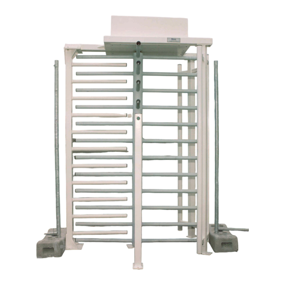
1. A concrete base suitable for external or internal use is required. Alternative types of base may be acceptable subject to discussion with Gunnebo technical personnel. 2. Fixing centres, it is not necessary to pre-drill the base to receive the RotaSec, drilling is carried out when the equipment is erected. - Page 38 Site Preparation Fig 5.2 RotaSec B120S (Shown with straight bar rotor) Straight bar rotor Stator bar „dead area‟ barrier Card reader / Push button pedestal Concrete of resistance class, at least, Floor Anchors to be drilled during fck,cube 30 N/mm .
- Page 39 Site Preparation Fig 5.3 RotaSec F90S (Shown with straight bar rotor) Straight bar rotor Stator bar „dead area‟ barrier Concrete of resistance class, at least, fck,cube 30 N/mm . Base to be flat and Floor Anchors to be drilled during level to +/- 5mm over the SpeedStile installation, 12mm dia x 100mm deep.
- Page 40 Site Preparation Fig 5.4 RotaSec F120S (Shown with straight bar rotor) Straight bar rotor Stator bar „dead area‟ barrier Concrete of resistance class, at least, fck,cube 30 N/mm . Base to be flat and Floor Anchors to be drilled during level to +/- 5mm over the SpeedStile installation, 12mm dia x 100mm deep.
- Page 41 Site Preparation Fig 5.5 RotaSec R90S (Shown with straight bar rotor) Canopy rain water down pipe Straight bar rotor Stator bar „dead area‟ barrier Walkway down light GRP canopy Concrete of resistance class, at least, Floor Anchors to be drilled during fck,cube 30 N/mm .
- Page 42 Site Preparation Fig 5.6 RotaSec R120S (Shown with straight bar rotor) Straight bar rotor Canopy rain water down pipe Walkway down light GRP canopy Stator bar „dead area‟ barrier Concrete of resistance class, at least, Floor Anchors to be drilled during fck,cube 30 N/mm .
- Page 43 Site Preparation Fig 5.7 RotaSec S90S (Shown with straight bar rotor) Straight bar rotor Canopy rain water down pipe Stator bar „dead area‟ barrier Walkway down light GRP canopy GRP side cabinet Concrete of resistance class, at least, Floor Anchors to be drilled during fck,cube 30 N/mm .
- Page 44 Site Preparation Fig 5.8 RotaSec S120S (Shown with straight bar rotor) Straight bar rotor Canopy rain water down pipe Walkway down light GRP canopy GRP side cabinet Stator bar „dead area‟ barrier Concrete of resistance class, at least, fck,cube 30 N/mm .
- Page 45 Site Preparation Fig 5.9 RotaSec F90D (Shown with straight bar rotor) Straight bar rotor Stator bar „dead area‟ barrier Concrete of resistance class, at least, fck,cube 30 N/mm Base to be flat and level to +/- 5mm over the SpeedStile footprint area.
- Page 46 Site Preparation Fig 5.10 RotaSec F90DI (Shown with straight bar rotor) Straight bar rotor Stator bar „dead area‟ barrier Concrete of resistance class, at least, fck,cube 30 N/mm . Base to be flat and level to +/- 5mm Floor Anchors to be drilled during over the SpeedStile footprint installation, 12mm dia x 100mm deep.
- Page 47 Site Preparation Fig 5.11 RotaSec F120D (Shown with straight bar rotor) Straight bar rotor Stator bar „dead area‟ barrier Concrete of resistance class, at least, fck,cube 30 N/mm . Base to be flat and level to +/- 5mm over the SpeedStile footprint area.
- Page 48 Site Preparation Fig 5.12RotaSec F120DI (Shown with straight bar rotor) Straight bar rotor Stator bar „dead area‟ barrier Concrete of resistance class, at least, fck,cube 30 N/mm . Base to be flat and level to +/- 5mm Floor Anchors to be drilled during over the SpeedStile footprint installation, 12mm dia x 100mm deep.
- Page 49 Site Preparation Fig 5.13 RotaSec R90D (Shown with straight bar rotor) Straight bar rotor Rain water down pipe Walkway down lights Stator bar „dead area‟ barrier GRP canopy Concrete of resistance class, at least, fck,cube 30 N/mm . Base to be flat and level to +/- 5mm over the SpeedStile footprint area.
- Page 50 Site Preparation Fig 5.14 RotaSec R90DI (Shown with straight bar rotor) Rain water down pipe Straight bar rotor Walkway down lights GRP canopy Concrete of resistance class, at least, fck,cube 30 N/mm . Base to be flat and level to +/- 5mm Floor Anchors to be drilled during over the SpeedStile footprint installation, 12mm dia x 100mm deep.
- Page 51 Site Preparation Fig 5.15 RotaSec R120D (Shown with straight bar rotor) Straight bar rotor Rain water down pipe Walkway down lights GRP canopy Stator bar „dead area‟ barrier Concrete of resistance class, at least, fck,cube 30 N/mm . Base to be flat and level to +/- 5mm over the SpeedStile footprint area.
- Page 52 Site Preparation Fig 5.16 RotaSec R120DI (Shown with straight bar rotor) Rain water down pipe Straight bar rotor Walkway down lights GRP canopy Stator bar „dead area‟ barrier Concrete of resistance class, at least, fck,cube 30 N/mm . Base to be flat and level to +/- 5mm over the SpeedStile footprint Floor Anchors to be drilled during area.
- Page 53 Site Preparation Fig 5.17 RotaSec F90D (Shown with straight bar rotor) Rain water down pipe Straight bar rotor Stator bar „dead area‟ barrier Walkway down lights GRP canopy GRP side cabinets Concrete of resistance class, at least, fck,cube 30 N/mm .
- Page 54 Site Preparation Fig 5.18 RotaSec S90DDI (Shown with straight bar rotor) Straight bar rotor Stator bar „dead area‟ barrier GRP side cabinets GRP canopy Concrete of resistance class, at least, fck,cube 30 N/mm . Base Floor Anchors to be drilled during to be flat and level to +/- 5mm installation, 12mm dia x 100mm deep.
- Page 55 Site Preparation Fig 5.19 RotaSec S120D (Shown with straight bar rotor) Rain water down pipe Straight bar rotor Walkway down lights GRP canopy GRP side cabinets Stator bar „dead area‟ barrier Concrete of resistance class, at least, fck,cube 30 N/mm .
- Page 56 Site Preparation Fig 5.20 RotaSec S120DI (Shown with straight bar rotor) Straight bar rotor Rain water down pipe Walkway down lights GRP side cabinets GRP canopy Stator bar „dead area‟ barrier Concrete of resistance class, at least, fck,cube 30 N/mm .
-
Page 57: Headroom
The power supply cable must be isolated until installation has been completed and must be terminated to a live supply by others. If Engineers from Gunnebo are erecting the unit, it is preferable to arrange concurrent attendance of the site Electrical Contractors to position the conduits and terminate cables. -
Page 58: General Details
General Details 1. Check level of the base, check the head room, corridor width, base and all critical dimensions. Refer to the installation figures. Tool Kit (If installation to be carried out by client) A tool kit, Pt No. 80061724, is required to assist with the installation of routines. The kit contains: Insert (M10 RX) M5 Pin Hex Insert... -
Page 59: Variations For "R" Models
Variations for “R” Models Omit the Fitting Instruction No.6 of the Setting to Work. Carry out the following procedure: Fit the GRP Roof Assembly using M10 x 50 RX Screws, Nuts and Washers. After this action continue to follow the Setting to Work Instructions. NOTE: On completion of the Installation routines, fit the Rain Water Down Pipe Cover by placing it in the hole provided in the GRP Roof Assembly. - Page 60 Fig 5.22 Installation – Model shown RotaSec F120S Fig 5.21 Installation – Model shown RotaSec F90S ......CCEC/ OM Manual RotaSec Titan 1.5 EN 08.2009...
- Page 61 ......CCEC/ OM Manual RotaSec Titan 1.5 EN 08.2009...
- Page 62 Fig 5.23 Frame Work installation details for the different Models Model B120S Basic Model F120S ......CCEC/ OM Manual RotaSec Titan 1.5 EN 08.2009...
- Page 63 Model R90S Model S90S ......CCEC/ OM Manual RotaSec Titan 1.5 EN 08.2009...
- Page 64 Model R120S Model S120S ......CCEC/ OM Manual RotaSec Titan 1.5 EN 08.2009...
- Page 65 Model F90D ......CCEC/ OM Manual RotaSec Titan 1.5 EN 08.2009...
- Page 66 Model F120D ......CCEC/ OM Manual RotaSec Titan 1.5 EN 08.2009...
- Page 67 Model R90D ......CCEC/ OM Manual RotaSec Titan 1.5 EN 08.2009...
- Page 68 Model R120D ......CCEC/ OM Manual RotaSec Titan 1.5 EN 08.2009...
- Page 69 Model S90D ......CCEC/ OM Manual RotaSec Titan 1.5 EN 08.2009...
- Page 70 Model S120D ......CCEC/ OM Manual RotaSec Titan 1.5 EN 08.2009...
- Page 71 Model F90DI ......CCEC/ OM Manual RotaSec Titan 1.5 EN 08.2009...
- Page 72 Model F120DI ......CCEC/ OM Manual RotaSec Titan 1.5 EN 08.2009...
- Page 73 Model R90DI ......CCEC/ OM Manual RotaSec Titan 1.5 EN 08.2009...
- Page 74 Model R120D ......CCEC/ OM Manual RotaSec Titan 1.5 EN 08.2009...
- Page 75 Model S90DI ......CCEC/ OM Manual RotaSec Titan 1.5 EN 08.2009...
- Page 76 Model S120DI ......CCEC/ OM Manual RotaSec Titan 1.5 EN 08.2009...
- Page 77 Fig 5.24 - Typical 90 Rotor Assemblies Fig 5.25 - Typical 120 Rotor Assemblies ......CCEC/ OM Manual RotaSec Titan 1.5 EN 08.2009...
-
Page 78: Electrical Connections
Card Reader Mounting Refer to Gunnebo Technical department for information and recommendations. Customer Connections On completion of the installation routines the RotaSec System must be connected to the Customer‟s services. Electrical Connections Note – The following routines must be carried out by a qualified electrician. -
Page 79: Testing After Installation
Testing after Installation On completion of the installation routines it is recommended that the following checks and tests be carried out. Power Switch ON the mains power and the mains circuit breaker unit. Mechanism Rotate the Rotor and check for parking position, restoring and damping for a minimum of non-consecutive operations in either direction. - Page 80 ......CCEC/ OM Manual RotaSec Titan 1.5 EN 08.2009...
- Page 81 Fig 5.28 – SNT1 Interface Connections Emergency/Fire Alarm 0v NC 24v Supply Power Fail output 0v System Reset 0v momentary signal Continuous Passage NO latching signal Passage Lock NO latching signal From LCM02 JP9 ......CCEC/ OM Manual RotaSec Titan 1.5 EN 08.2009...
- Page 82 ......CCEC/ OM Manual RotaSec Titan 1.5 EN 08.2009...
- Page 83 Optional Equipment Figure 5.30 and 5.31 give details of how to install optional items (i.e. Status Lights and Pushbuttons) for the F and R model ranges. Fig 5.30 - Status Lights ......CCEC/ OM Manual RotaSec Titan 1.5 EN 08.2009...
- Page 84 Fig 5.31 - Optional Pushbuttons ......CCEC/ OM Manual RotaSec Titan 1.5 EN 08.2009...
- Page 85 Card readers When Card readers are to be fitted they should be mounted and the cables routed to the respective terminal points. Bottom Bearing The Bottom Bearing comprises a single steel ball running in a housing. Remember to insert the ball when the rotor column is fitted. The bearing MUST be charged with the special grease supplied.
-
Page 86: Section 6 Maintenance
Section 6 Maintenance Maintenance General Care The RotaSec Rotating Door should be cleaned and greased at regular intervals, using the following approved materials. Routine Cleaning, all finishes Cleaning agent. Soap or mild detergent water. Action: Sponge rinse with clean water, wipe dry as necessary Fingerprints Cleaning agent: Soap or warm water or organic solvent (acetone, alcohol, genclene) -
Page 87: Routine Maintenance
Routine Maintenance General Indications The mechanism should be inspected and cleaned at regular intervals in order to maintain the components in good working order and to check for signs of wear. Note - The following indications refer to an installation where the average number of transits per year is equal to one million. - Page 88 Components Annual Checks (Operations to be carried out with the power supply and BBU disconnected) Cables and Connectors (Operations to be carried out with the power supply and BBU disconnected) Check that the wire connectors are firmly attached. Check that the terminals are fully tightened. ...
-
Page 89: Fault Finding
Down light In the event that lamp replacement is necessary, remove the Down Light cover by unscrewing it and lower the reflector assembly carefully. Remove and replace the lamp. Note - Care should be taken with lamp replacement to ensure that the fingers do not come in contact with the glass of the lamp Fault Finding During normal operation of the mechanism, the control logic displays the status of certain signals. - Page 90 Fault Finding Symptom Check Action Adjust restoring mechanism Adjust damping mechanism Restoring and Damping Rotor will not park if on maximum mechanisms setting replace with new. Adjust solenoids Solenoids, Locking Pawls Adjust locking pawls, if faulty Rotor over spins and Sensor Card replace.
-
Page 91: Section 7 Spare Parts
Section 7 Spare Parts Spare Parts Recommended Spare Parts Quantities listed are per RotaSec over a 24 month period. Table 7.1 – Recommended Spare Parts Code Description SE-LA-MU-0007 Bulb 35W Clear 12V SE-FU-MU-0013 Fuse Mains 24mm 3A SE-SO-MU-0013 Locking Solenoid SA-DA-MU-0003 Damper (if fitted) SM-SH-MU-0037... -
Page 92: Section 8 Table Appendices
Section 8 Table Appendices Table Appendices Table 8.1 Decimal, Hexadecimal and Decimal Conversion Table Binary Binary Binary Binary 00000000 01000000 10000000 11000000 00000001 01000001 10000001 11000001 00000010 01000010 10000010 11000010 00000011 01000011 10000011 11000011 00000100 01000100 10000100 11000100 00000101 01000101 10000101 11000101 00000110... -
Page 93: Firmware Version - Fbcbqmyr110
Table 8.2 – Factory Set Parameter Values Firmware Version - FBCBQMYR110 Location Def. 00 Def 01 Def.02 Variable Note Description Pmagneti See Table 1 Magnets polarity BMT/SMT 1 = locked 2 = unlocked Mode A at start-up 3 = reader 4 = temporised 1 = locked 2 = unlocked... - Page 94 TABLE 1: PMagneti Bit 7 Bit 6 Bit 5 Bit 4 Bit 3 Bit 2 Bit 1 Bit 0 Solenoid Solenoid Polarity Polarity Side B Side A 0 = FL 0 = FL 1 = FS 1 = FS TABLE 2: EnableAll - PMaskRL1 - PMaskRL2 (high+low) EnableAll(high) - PMaskRL1H - PMaskRL2H Bit 7 Bit 6...
-
Page 95: Firmware Version (Fbcbqmyr123)
Firmware Version (FBCBQMYR123) Def. Def. Def. Parameter Note Description Loc. PMagneti see table 1 Magnets polarity FL/FS 1. Locked 2. Unlocked Mode A at start-up 3. Reader 4. Timing 1. Locked 2. Unlocked Mode B at start-up 3. Reader 4. Timing EnableAll see table 2 Alarms enabling at start-up (high) - Page 96 TABLE 1: PMagneti Bit 7 Bit 6 Bit 5 Bit 4 Bit 3 Bit 2 Bit 1 Bit 0 Solenoid Solenoid Polarity Polarity Side B Side A 0 = FL 0 = FL 1 = FS 1 = FS TABLE 2: EnableAll - PMaskRL1 - PMaskRL2 (high+low) EnableAll(high) - PMaskRL1H - PMaskRL2H Bit 7 Bit 6...
-
Page 97: Onformity
Section 9 Declaration of Conformity Declaration of Conformity ......CCEC/ OM Manuals RotaSec Titan 1.5 08.2009... - Page 98 Notes ....... CCEC Product Data\CCEC O&M Manuals ClearSec 1.3 09.2008...
- Page 99 Notes ......CCEC/ OM Manual RotaSec Titan 1.5 EN 08.2009...
- Page 100 Gunnebo AB, Box 5181, SE-402 26 Goteborg, SWEDEN. Tel +46-31 83 68 00, Fax +46-31 83 68 10 www.gunnebo.com Note: In pursuit of its policy of continuous refinement and improvement, Gunnebo Entrance Control Ltd reserves the right to modify design and details......
Need help?
Do you have a question about the RotaSec B120S and is the answer not in the manual?
Questions and answers