Advertisement
Quick Links
Copy OEM Logo Here
Instructional Symbols / Definitions
Basic Required Tools
Ratchet
Torque Wrench
Slotted Screwdriver
Notes to the installer:
1
Read the entire Installation Instructions prior to beginning the installation of the part.
2
Make sure the vehicle is completely clean and dry in the area(s) the part is to be installed.
3
Ensure the vehicle is properly protected in the area(s) that the accessory is to be installed.
4
NEVER place tools on painted surfaces, seating surfaces, dash pad, console or floor carpet/mats.
5
Always wear appropriate personal protective equipment, including gloves, safety glasses, etc., when required.
6
Record radio presets prior to disconnecting battery power, if needed.
7
Ensure the transportation fuse is set to "ON" before starting the install.
8
Roll down the driver's window and adjust the power seats (if applicable) prior to disconnecting battery power, if needed.
*550-0670-000*
550-0670-000 Rev. 004
Vehicle Model
Model Year
Part No.
(→)
Language English
Rev. Date
Denotes warnings that may lead to serious
physical injury or vehicle damage
Denotes cautions to be taken to avoid
physical injury or electronic component
damage
Denotes cautions to be taken to avoid
vehicle and component damage
M10
Nylon Panel Removal
10mm Socket
Tool
Side Cutters
Pliers
Genuine Accessories
Sportage
Accessory:
2017~
D9062 ADU00
D9062 ADUP0
11/23/2015
Denotes quality processes to be checked
prior to moving to the next step
Denotes specific tools that are necessary
to complete a step
N
O
Denotes important information to be
T
reviewed during the step
E
#2 Phillips Screwdriver
T20 Torx Driver
T20
T20 Torx Socket
Tape Measure
Revision Date
11/23/2015
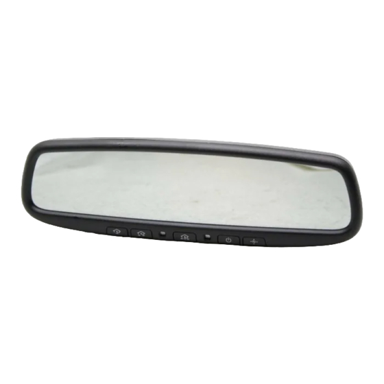
Mirror, Auto-dim with HL4 Comp.
Difficulty:
( B )
Difficulty stated above reflects the minimum level of
Note:
expertise required to install the accessory:
(A) Customer
(B) Dealer Technician
(C) Master Technician or Specialist
Denotes personal protective equipment (PPEs) that
may be required for a step. Examples of safety
equipment icons noted below:
Glasses
Gloves
Mask
Hearing Protection
T20
Page 1 of 17
Advertisement

Related Manuals for Kia D9062 ADUP0


Summary of Contents for Kia D9062 ADUP0
- Page 1 Difficulty: ( B ) Part No. D9062 ADU00 Copy OEM Logo Here (→) Difficulty stated above reflects the minimum level of D9062 ADUP0 Note: expertise required to install the accessory: Language English Rev. Date 11/23/2015 (A) Customer (B) Dealer Technician...
- Page 2 Genuine Accessories Kit Overview Description Mirror, Auto-dimming w/ HL4 & Compass Hardware Kit Hardware Kit Contents A-Pillar Tether Clip Harness Wire Cover Foam Tape* T-Taps* (85815 C1000 - White) Wire Ties* Installation Instruction Quick Ref. Guide * Indicates extra components intentionally included in kit as spares. Hardware Total Follow instructions for proper placement of each component.
-
Page 3: Electrical Connection Procedure
Genuine Accessories Special Instructions Electrical Connection Procedure Wire Appearance Disconnecting Connectors Wires may be solid color, or striped (tracer). The first color in the description When disconnecting the wires, grasp the connectors, not the wires. indicates the base color of the wire; the second indicates the stripe. Example: Example: Solid color wire... - Page 4 Genuine Accessories Ratchet and 10mm Socket 1. Ensure the correct part is being installed. Verify the part number on 1. Carefully pull the front of the driver-side door seal back to allow the installation orders with the part number on the kit box label. removal of the A-pillar trim panel 2.
- Page 5 Genuine Accessories Pliers 1. Continue removing the A-pillar trim panel by pulling the top out toward 1. Using pliers, pull the remaining portion of the A-pillar tether clip out of the passenger side of the vehicle, until remaining one (1) clip is the A-pillar, and discard.
- Page 6 Genuine Accessories T20 Torx Driver #2 Phillips Screwdriver 1. Using a T20 Torx Driver, loosen the screw on the mirror mount. 1. Open sunglass holder in the overhead console, exposing two (2) 2. Gently pull the mirror upwards in a parallel direction to the windshield. Philips screws, and with a #2 Philips screwdriver, remove them.
- Page 7 Genuine Accessories #2 Philips Screwdriver #2 Philips Screwdriver & Nylon Panel Removal Tool Phillips Screws 1. Using a screwdriver, remove the three (3) Philips screws from the 1. Remove one (1) Philips screw from lower right corner of lower dash outside surface of the lower dash trim panel.
- Page 8 Genuine Accessories 1. Plug the 5-pin connector from the provided one (1) mirror harness into 1. Wrap one (1) foam tape around the mirror harness connector, as shown. the harness lead extending out from the mirror. CAUTION: Ensure 5-pin connector is securely installed. Nylon Panel Removal Tool 1.
- Page 9 Genuine Accessories Tape Measure & Nylon Panel Removal Tool Side Cutters Foam Tape 1. Hold the mirror harness against the headliner and wrap one (1) foam 1. Route mirror harness down the A-pillar into the dash, toward engine tape around the harness where it meets the corner of the A-pillar. side of fuse panel.
- Page 10 Genuine Accessories Pin 19 Pin 20 Pin 23 Brown Connector C 1. Locate Connector C (38 pin connector) on the front side of the 1. Locate Pin 23 (BROWN wire) of Connector C. junction block (furthest side from the engine). CAUTION: Ensure the correct wire is identified.
- Page 11 Genuine Accessories Pin 3 Grey w/ Orange Connector C 1. Continue working with Connector C (51 pin connector) on the front side of 1. Locate Pin 3 (GRAY w/ ORANGE wire) of Connector C. the junction block (furthest side from the engine). CAUTION: Ensure the correct wire is identified.
- Page 12 Genuine Accessories 10mm Socket & Ratchet 10mm Socket & Torque Wrench Ground Ring Secured under 10mm 10mm Bolt Bolt 1. Locate the 10mm bolt at the lower left corner of the steel knee bolster. 1. Place the ground ring of the mirror harness onto the removed 2.
- Page 13 Genuine Accessories Function Check Function Check Compass 1. Cover the forward-facing photocell with a dark cloth or towel. 1. Verify that a direction or calibrate (such as "NE" or "C") is displayed 2. Turn the ignition to "ON". in the display window. If not, ensure the compass feature is 3.
- Page 14 Genuine Accessories Reassmble Vehicle 1. Re-install, in reverse order, all remaining trim panels removed 1. Place the provided one (1) Quick Reference Guide in the glove box. during installation. 3. Clean fingerprints, smudges, etc. from mirror and windshield. CAUTION: DO NOT spray glass cleaner or other cleaning liquid directly on the mirror as it may damage the electronics.
- Page 15 Genuine Accessories Visual Check Item to be Checked Result Negative battery terminal re-tightened Battery cable is correctly fastened to the negative terminal. Nut is properly torqued. Mirror Torx screw replaced and re-tightened Screw is tightened and properly torqued. Harness Mirror harness connectors are properly connected. T-Tap spade connectors are properly seated.
- Page 16 Genuine Accessories Troubleshooting Issue / Concern Items to be Checked Mirror does not power up Confirm constant power circuit is properly connected Circuit should have 12V power with ignition in "OFF" -Check that mirror harness is properly connected at mirror -Check that T-tap is connected to the proper wire -Check that T-Tap is fully crimped -Check that male spade is correctly inserted in T-tap.
- Page 17 Genuine Accessories Wiring Diagram Smart Junction Box Connector "C" SJB_FLRS_C Pin 3 - Grey w/ Orange BLK w/ WHT Interior lamp circuit Pin 23 - (Grey w/ Orange wire) Brown Module 1 circuit (Green w/ Orange wire) Mirror connector Gauge Color Function Circuit...
Need help?
Do you have a question about the D9062 ADUP0 and is the answer not in the manual?
Questions and answers