
Related Manuals for Windrock Spotlight A3910

Summary of Contents for Windrock Spotlight A3910
- Page 1 Engine Spotlight Monitoring System: Spotlight Controller Engine Spotlight PUC Module USER MANUAL...
- Page 2 Your license agreement with Windrock Incorporated authorizes the number of copies which can be made and the computer systems on which they may be used. Any unauthorized duplication or use of Windrock software or firmware in whole or in part, in print, or in any other storage and retrieval system, is forbidden.
-
Page 3: Table Of Contents
Table of Contents A3910 Spotlight Controller Connections Operation Spotlight Peripheral Universal Connection (PUC) Module Features Connections Operation Included Accessories General External Accelerometers Magnetic Pickup Sensor Controller WiFi Antennas Spotlight Trunk Cable Spotlight Magnetic Pickup Cable Spotlight Armored Accelerometer Cable Worm Drive Clamp Kits Base Plate with 1/4-20 Stud and Adhesive 3.10 Accelerometer Isolation Pads with 1/4-28 Stud and Adhesive Optional Accessories... - Page 4 When pressure washing, be cautious on length of time and intensity of spray on all parts of the system, including sensors and cabling. If parts of a Spotlight system were removed in order to perform cleaning and/or maintenance, contact Windrock Product Support at 865-330-1100 and ask for Spotlight Installation Support to verify operation.
-
Page 5: A3910 Spotlight Controller
Windrock may compromise system integrity. TDC Input – Non-incendive 3-pin input for TDC. In order for the Windrock Spotlight system to operate properly, an accurate TDC signal is required. Use ONLY magnetic pickup sensors with entity parameters as described in control drawings. The magnetic pickup generates a signal as it crosses an artifact (pin or hole) in a spinning steel disk such as the flywheel. -
Page 6: Operation
Section 5, System Installation. WARNING: If the Controller is not operating properly, then unit must be returned to Windrock for repair service. Contact your sales representative or Windrock directly. AVERTISSEMENT : Si le contrôleur ne fonctionne pas correctement, puis doit être renvoyé à Windrock des réparations. -
Page 7: Spotlight Peripheral Universal Connection (Puc) Module
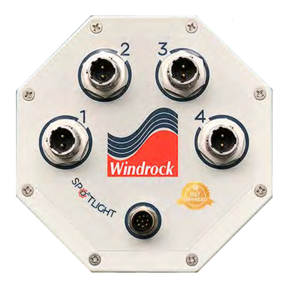
Figure 2-1, A3940 PUC Module Accelerometer Connections (x4) – Non-incendive 2-pin input used to connect to accelerometer cables. Connection to any other equipment or using any other cables other than those specified by Windrock may compromise system integrity. For further information, see Spotlight Datasheet. -
Page 8: Magnetic Pickup Sensor
With an A6400 Portable Analyzer and A6420 Shaft Encoder, you can verify the offset of the target from TDC and enter this into the geometry setup in the Windrock MD software. TDC should be marked on the flywheel sufficient for the timing light to illuminate when the machine is running. -
Page 9: Spotlight Trunk Cable
47, Code of Federal Regulations, part 15.247.) In general, it is the responsibility of the installer and operator, respectively, to ensure that legal requirements for installation and operation are followed. Contact Windrock for information on how to reduce controller transmitter power. -
Page 10: Base Plate With 1/4-20 Stud And Adhesive
Section 3 Section Items listed in Section 4 are not standard and therefore must be purchased separately. If interested, contact Windrock Sales for a quote. NOTE: THE SAFETY OF ANY SYSTEM INCORPORATING THE EQUIPMENT IS THE RESPONSIBILITY OF THE INSTALLER OF THE SYSTEM. -
Page 11: T-Adapter Connector
4.8 Shaft Encoder Windrock’s Shaft Encoder is used to provide the TDC phasing signal to Portable Analyzer. The Encoder generates a pulse per revolution (PPR) signal for tracking crankshaft motion. Spotlight Controllers connect to the Shaft Encoder to allow the Portable Analyzer to reference machine TDC. - Page 12 SUBSTITUTION OF COMPONENTS MAY IMPAIR SUITABILITY FOR CLASS 1, DIVISION 2 ALL WIRING MUST BE IN ACCORDANCE WITH APPROPRIATE SECTIONS OF THE NATIONAL ELECTRICAL CODE AND/OR IN ACCORDANCE WITH THE CANADIAN ELECTRICAL CODE AND IN ACCORDANCE WITH THE AUTHORITY HAVING JURISDICTION. Refer to Spotlight Datasheet for details on hazardous location ratings.
-
Page 13: Installation Overview
5.3 Installation Overview Figure 5-1, Single Controller Installation Figure 5-2, Multi-Controller Installation Tools Needed: • cordless drill • No. 25 drill bit • 5/8-18 UNF-2A tap • 1/4-28 flat bottom tap • cell phone • Infrared thermometer • 1/4” drill bit •... - Page 14 AND wall thickness is larger than 0.125”, customer must supply four 1/4”-20 screws longer than supplied in the Windrock kit (1/4”-20 x 1”). Assemble Gateway. Install router on DIN rail and mount feet on bottom of enclosure. For details, see Section 5.7.
- Page 15 (supplied by customer). If wall thickness is larger than 0.125”, customer must supply four 1/4”-20 screws longer than supplied in the Windrock kit (1/4”-20 x 1”). Seal penetrations according to site best practices. 18) Customer must supply a source of SELV LPS 24VDC Power at desired controller mounting location. For details, see Section 5.6.
- Page 16 A 24” long ground strap is attached onto the PUC mounting bar. The ground strap includes a ring terminal for a 1/4” diameter screw. In order to effectively divert EMI that could affect system performance, the ground strap must make solid electrical contact with the engine Earthing System. 1/4-20 screws have been provided with the system.
-
Page 17: Magnetic Pickup Mounting
A3940 locally as its status and operation can be observed within the Cloud and accessed from Windrock Enterprise and downloaded to Windrock MD. 5.4 Magnetic Pickup Mounting When using the magnetic pickup for TDC (top dead center) triggering in reciprocating machine analysis, it is extremely important that the pickup triggers data acquisition exactly at TDC. -
Page 18: Controller Mounting
5.6 Power Requirements Windrock Spotlight is designed to be powered from an approved SELV LPS 24VDC power source. Locations that do not have 24VDC available will require the addition of 24Vdc power supplies rated for the installed location. Refer to the Spotlight Datasheet for further details. -
Page 19: Gateway Mounting
The Gateway can be structurally mounted in two different ways. The first way (Option # 1, Figure 5-7) uses two slotted aluminum mounting bars that accept 10- 32 screws. Windrock recommends using this mounting method. Attach the mounting bars to the enclosure using the flathead screws included with the plastic mounting feet (Option # 2, Figure 5-8). -
Page 20: Puc Mounting
Drill holes - If permissible, drill and tap 1/4-20 holes at the mounting location or a mounting plate (supplied by customer). If wall thickness is larger than 0.125”, customer must supply four 1/4-20 screws longer than supplied in the Windrock kit (1/4”-20 x 1”). If necessary, seal penetrations according to site best practices. Refer to Section 7 for PUC Module mounting drawings. -
Page 21: Maintenance And Cleaning
Windrock Product Support at 865-330-1100 and ask for Spotlight Installation Support to verify operation. The Windrock Spotlight contains no user serviceable parts and requires no routine maintenance. Repair and support are provided by Windrock Inc. only.
Need help?
Do you have a question about the Spotlight A3910 and is the answer not in the manual?
Questions and answers