
Related Manuals for Windrock 6400

Summary of Contents for Windrock 6400
- Page 1 6400 Portable Analyzer Reference Manual Rev. 1.3 7/24/2017 Windrock, Inc. 1832 Midpark Road, Suite 102 Knoxville, TN 37921 Phone: 865.330.1100 Fax: 865.330.1101 www.windrock.com...
-
Page 2: Table Of Contents
Goals ................................2 Engine Data Collection Locations ....................... 3 Compressor Data Collection Locations ....................... 4 Batteries and Charging ..........................7 6400 Analyzer ............................8 Adjusting Analyzer Screen Brightness ...................... 10 Adjusting Analyzer Date/Time ........................11 Encoder / Wireless Transmitter ......................... 12 Encoder / Wireless Transmitter Functions .................... -
Page 3: Why An Analysis Program
6400 Reference Manual Why an Analysis Program? The purpose of any Analysis Program is to assemble quality systems and personnel to perform regular assessments of the condition and performance of the operation’s equipment assets. Testing and analysis, when performed with consistency and regularity, can be a valuable tool for helping predict and pinpoint mechanical or other problems that may be occurring within a process system to help reduce costly down or offline time as well the repair or replacement of mechanical parts or components. -
Page 4: Engine Data Collection Locations
6400 Reference Manual Engine Data Collection Locations Engine Data Collection Point Examples... -
Page 5: Compressor Data Collection Locations
6400 Reference Manual Compressor Data Collection Locations Compressor Pressure and Infrared Data... - Page 6 6400 Reference Manual Compressor Vibration Data...
- Page 7 6400 Reference Manual Compressor Ultrasonic Data...
-
Page 8: Batteries And Charging
6400 Reference Manual Batteries and Charging The 6400 analyzer kit comes standard with two different sized batteries. The analyzer uses the large battery, while the encoder / wireless transmitter & strobe (timing) light use the smaller battery. Note: Both batteries utilize the same battery charger that is provided with the 6400 analyzer kit. -
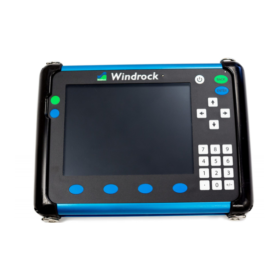
Page 9: 6400 Analyzer
Windrock analyzers come in several configurations ranging in complexity depending upon the types of machinery to be tested and data to be collected:... - Page 10 6400 Reference Manual...
-
Page 11: Adjusting Analyzer Screen Brightness
Adjusting Analyzer Screen Brightness The ability to adjust the brightness of the analyzer is available via the Utilities menu on the 6400-analyzer screen. Once Utilities is selected, a menu list will be displayed on the analyzer. Select option 2 (System setup) from the main utilities menu and then option 2 (Display) from the sub menu. -
Page 12: Adjusting Analyzer Date/Time
Adjusting Analyzer Date/Time The ability to adjust the date/time that displays on the analyzer is available via the Utilities menu on the 6400 analyzer screen. Once Utilities is selected, a menu list will be displayed on the analyzer. Select option 2 (System setup) from the main utilities menu and then option 3 (Date/time) from the sub menu. -
Page 13: Encoder / Wireless Transmitter
The short antenna is for blue tooth connection that is currently used for firmware updates and is not required for normal operation. The long antenna is for sending speed information to the 6400 and is required when using the wireless function. - Page 14 Channel 7 = 921.37 MHz Note: If a 6320 analyzer is running in the general vicinity of a 6400 analyzer interference will occur with the 6400 encoder / wireless transmitter signal if it is set to Channel 7. The 6320 transmitter signal is not compatible with the 6400 hardware.
-
Page 15: Encoder / Wireless Transmitter Functions
6400 Reference Manual Encoder / Wireless Transmitter Functions Encoder (EN) – Requires access and connection to the crank or a shaft running at the same speed. - Page 16 6400 Reference Manual Magnetic Pickup (MP) - Uses a magnetic pickup plugged into an accelerometer cable to see a target on the flywheel. The encoder can automatically determine whether a pin or hole is being detected and polarity of the sensor wires is not critical so long as both wires have no reference to ground.
- Page 17 6400 Reference Manual Setting DEG (degree) The MP mode can also be configured to add a second magnetic pickup for detecting degree signals by pressing the button which toggles between TDC only mode and TDC & DEG mode. Note: Before changing to this mode, the user must have already set TDC having a stable RPM.
- Page 18 6400 Reference Manual Optical Pickup (OP) - This function uses an optical pickup that is plugged into the TDC port and it is triggered from a piece of reflective tape that is mounted on the flywheel. Like the MP mode, this mode also has a button which toggles between TDC only mode and TDC &...
- Page 19 6400 Reference Manual Prox Negative (P-) - This mode accommodates a negative supply proximity probe that is looking at a hole or pin target to obtain a TDC (Common with Bentley panels). The threshold adjustment operates the same as the MP mode except that It has a wider range (0-40).
- Page 20 Any changes or modifications not expressly approved by the party responsible for compliance could void the user’s authority to operate the equipment. This device has been designed to operate with the antennas supplied by Windrock. Antennas not supplied by Windrock are strictly prohibited for use with this device. The required antenna impedance...
-
Page 21: Selecting A Wireless Transmitter Channel
When picking a channel, the one with the least amount of RF traffic is most desirable. To determine this, perform the following steps… 1) With the wireless encoder / wireless transmitter off, on the 6400 analyzer open the Utilities menu and select option 5 (Encoder). -
Page 22: Magnetic Pickup / Optical Sensor
6400 Reference Manual Magnetic Pickup / Optical Sensor Both of these methods works well to provide a once-per-turn synchronization reference by tracking the revolution of a reflective reference such as a hole, pin or reflective tape. Magnetic Pick-up • The magnetic pick-up will cause the sync light to flash at the center of the hole or pin target. -
Page 23: Cables
6400 Reference Manual Cables The 6400 analyzer kit comes standard with two cable types. Optional cables are available for purchase separately. Multipurpose (A6460-CBL-0-06) (White End) Used for connection of the following end devices: • Pressure Sensors • Ultrasonic/IR Sensor •... -
Page 24: Strobe (Timing) Light
6400 Reference Manual Strobe (Timing) Light When using a permanently mounted magnetic pickup you can make a note of the degree offset from the bottom right of the screen and enter this offset into the machine geometry setup. Note: The analyzer currently retains the last degree offset that was set using the timing light. If using a permanently mounted magnetic pickup located at TDC be sure to set the strobe light offset to 0.00 degrees... -
Page 25: Engine Pressure Transducer
6400 Reference Manual Engine Pressure Transducer The engine 4-20 mA strain gauge pressure sensor comes as an air-cooled sensor and can be used for high temperature applications such as diesel. The range of this sensor is 0 – 5000 PSIG. -
Page 26: Compressor Pressure Transducer
Compressor Pressure Transducer The compressor 4-20 mA sensor is the standard sensor for collecting compressor pressure measurements with the Windrock 6400 analyzer. The pressure transducer is typically connected to a Kiene valve or other indicator valve type on the compressor cylinders. -
Page 27: Pressure Transducer Calibration (Zeroing The Sensor)
6400 Reference Manual Pressure Transducer Calibration (Zeroing the Sensor) Pressure transducers should be calibrated prior to connection to a machine when taking data. To calibrate a pressure transducer simply plug the sensor into the analyzer and press the Utilities function key, then select option 3 (Calibrate sensors) from the menu. -
Page 28: Primary Ignition
6400 Reference Manual Primary Ignition The primary ignition pick-up is used to capture and accurately measure primary ignition voltage when access is readily available. You can measure up to 500 volts with the built in 100 :1 attenuator. The primary ignition pick-up is clipped to the N, G, P, V or other lead in the junction box depending on the ignition system using the red alligator clip. -
Page 29: Secondary Ignition
A difference in the 6320 and 6400 is spark collection. Now, you will see only the detailed spark trace in real time and be able to view the ionization voltage, arc duration and timing of the ignition spark. -
Page 30: Accelerometer
The accelerometer sensor provided with the Windrock 6400 analyzer has a sensitivity of 100 mV /g and is the small sensor in the kit when compared to the velocity sensor. -
Page 31: Velocity Probe
(frames, cylinders, skids). The velocity probe provided with the Windrock 6400 analyzer has a sensitivity of 100 mV /g and is the large sensor in the kit when compared to the accelerometer. -
Page 32: Ultrasonic / Infrared Temperature
6400 Reference Manual Ultrasonic / Infrared Temperature Note: When setting the gain in the analyzer for the ultrasonic the setting is stored globally in the analyzer. This means that when you set the gain using the ultrasonic, when you go to take data on another machine the gain will still be set to where it was when last used. -
Page 33: Ultrasonic Gain Adjustment
6400 Reference Manual Ultrasonic Gain Adjustment The ultrasonic sensor gain is adjusted via the Utilities menu on the 6400-analyzer screen. Once Utilities is selected, a menu list will be displayed on the analyzer. Select option 4 (Ultrasonic gain) from the Utilities menu and the adjustment box below will display on the analyzer screen. - Page 34 6400 Reference Manual The following example illustrates the various data trace representations that may be observed while adjusting the ultrasonic gain and should be used for comparison when setting the ultrasonic gain to an acceptable level.
-
Page 35: Headphones
6400 Reference Manual Headphones The 6400 analyzer is available with optional accessory headphones. When used in conjunction with the ultrasonic sensor the headphones allow the user to listen and detect internal and external gas leakage during the walk-around assessment. 1) Plug the headphones into the headphone jack port on the 6400 analyzer. - Page 36 6400 Reference Manual 4) Select option 7 “Audio playback”. 5) Adjust the volume knob on the headphones to the desired sound level if available. On the analyzer adjust the volume bar to the desired setting using the arrows on the analyzer keypad.
- Page 37 6400 Reference Manual 6) Adjust the ultrasonic gain by accessing the Utilities function key and then selecting option 4 (Ultrasonic gain). 7) Use the arrows on the analyzer to adjust the gain to the desired setting and then select the ENTER...
-
Page 38: Va Kit Additional Items
Furthermore, it allows for easy data collection off Bently style panels. Components include: Additional Windrock MD software functionality Four (4) accelerometer input cables, 10-ft. (LEMO to 2-pin MS) Five (5) proximity probe input cables, 10-ft. (LEMO to BNC-M)
Need help?
Do you have a question about the 6400 and is the answer not in the manual?
Questions and answers
Can the IEPE power be shut off?