Table of Contents
Advertisement
Quick Links
Advertisement
Table of Contents

Related Manuals for FRC ICA900


Summary of Contents for FRC ICA900
-
Page 1: Intercom System
ICA900 Rev150324 Document Number: XE-ICA9PM-R0A INTERCOM SYSTEM Model ICA900 Push-To-Talk Control Module Speaker Box Hands Free Control Module FIRE RESEARCH CORPORATION www.fireresearch.com 26 Southern Blvd., Nesconset, NY 11767 TEL 631.724.8888 FAX 631.360.9727 TOLL FREE 1.800.645.0074... -
Page 2: Table Of Contents
Control Module ....................10 Cables ........................11 List of Figures Figure 1. ICA900 Control Module Dimensions ............5 Figure 2. ICA900 Speaker Box Dimensions .............. 7 Figure 3. ICA900 Operation ..................9 Figure 4. ICA900 Control Module Wiring .............. 10... -
Page 3: Introduction
ICA900 Rev150324 INTRODUCTION Overview The ACT (Always Clear Talking) intercom system from FRC has updated noise cancellation circuitry that essentially eliminates acoustical background noise. The compact control module is separate from the speaker box to provide installation flexibility. Multiple mounting options that only require a two-wire connection between stations, and hands-free remote operation make this intercom especially useful for aerial applications. -
Page 4: Installation
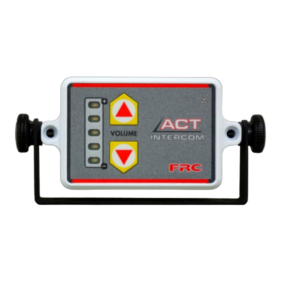
ICA900 Rev150324 INSTALLATION Install Control Module The control module is mounted with a bracket or to the surface with a panel cutout for the connector. Bracket Mount Note: The mounting bracket can be removed by unscrewing the adjustment knobs at the side of the control module. -
Page 5: Figure 1. Ica900 Control Module Dimensions
4 3/8" Surface Mounted 1 7/8" 5 1/8" 2 7/8" Panel Cutout 1/4" radius max 1 1/2" 1 3/8" Mounting holes are clearance or tapped 2 3/8" for 10-32 screws. 2 5/16" 4 5/8" Figure 1. ICA900 Control Module Dimensions... -
Page 6: Install Speaker Box
ICA900 Rev150324 Install Speaker Box The speaker box is mounted with a bracket or to the surface with a feed through hole for the cable. Bracket Mount Note: The mounting bracket can be removed by unscrewing the adjustment knobs at the side of the control module. -
Page 7: Figure 2. Ica900 Speaker Box Dimensions
Ensure that the screws do not 4 1/2" bottom out in the hole. 2 1/4" Panel mounting 1/2" holes are clearance 4 1/2" for 10-32 screws. Figure 2. ICA900 Speaker Box Dimensions... -
Page 8: Operation
ICA900 Rev150324 OPERATION The Push-To-Talk modules are always in receive mode. The Push-To-Talk button must be pressed to put the module into transmit mode. The hands free module is always in transmit mode. To talk on the intercom the operator speaks and the intercom transmits. It is in receive mode when another module is transmitting. -
Page 9: Figure 3. Ica900 Operation
Transmit LED Microphone Refer to Wiring Section for detailed information. Two-Way System Either control module can be hands free. Power Power Three-Way System Any one control module can be hands free. Power Power Alternate Connection Power Figure 3. ICA900 Operation... -
Page 10: Wiring
Supply Ground 3/Blue Speaker 4/Brown Speaker 5/White Line 1-A 6/Green Line 1-B 7/Plug Line 2-B 8/Plug Line 2-A Jumper to Pin 10 Jumper to Pin 9 Jumper to Pin 12 Jumper to Pin 11 Figure 4. ICA900 Control Module Wiring... -
Page 11: Cables
- Extension cable standard lengths are 20 feet (-C20A). Longer cables are available. - Provide enough slack in the cable when using the mounting bracket for the control module or speaker box to be adjusted as needed. Figure 5. ICA900 Cables...
Need help?
Do you have a question about the ICA900 and is the answer not in the manual?
Questions and answers