Table of Contents
Advertisement
Quick Links
Document Number:
XE-ICA1PM-R0A
AMBULANCE/RESCUE VEHICLE
SURFACE MOUNT SERIES
MODELS ICA200, ICA300
FLUSH MOUNT SERIES
MODELS ICA400, ICA500
TEL 631.724.8888 FAX 631.360.9727 TOLL FREE 1.800.645.0074
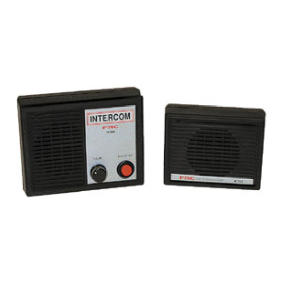
INTERCOM
MODEL ICA100
ICA100
FIRE RESEARCH CORPORATION
www.fireresearch.com
26 Southern Blvd., Nesconset, NY 11767
ICA200/300
1
ICA100 Rev171109
ICA400/500
Advertisement
Table of Contents

Subscribe to Our Youtube Channel
Related Manuals for FRC ICA100 Series


Summary of Contents for FRC ICA100 Series
- Page 1 ICA100 Rev171109 Document Number: XE-ICA1PM-R0A INTERCOM AMBULANCE/RESCUE VEHICLE MODEL ICA100 SURFACE MOUNT SERIES MODELS ICA200, ICA300 FLUSH MOUNT SERIES MODELS ICA400, ICA500 ICA100 ICA200/300 ICA400/500 FIRE RESEARCH CORPORATION www.fireresearch.com 26 Southern Blvd., Nesconset, NY 11767 TEL 631.724.8888 FAX 631.360.9727 TOLL FREE 1.800.645.0074...
-
Page 2: Table Of Contents
INTRODUCTION ...................... 3 Overview ........................ 3 Features ........................3 Specifications ......................3 GENERAL INSTALLATION NOTES ............... 4 ICA100 SERIES INSTALLATION ................5 Pre-Installation ....................... 5 Install Remote Station .................... 5 Install Master Station .................... 5 ICA200/300 SERIES INSTALLATION ..............8 Pre-Installation ....................... -
Page 3: Introduction
Overview Fire Research intercoms are designed to meet rescue and fire service requirements for two or three-way voice communications system. The ICA100 series intercom systems are designed for use inside ambulances and rescue vehicles. The ICA200/300 surface mount and ICA400/500 flush mount series intercom systems are weather- resistant and specifically designed for outside use on fire service apparatus. -
Page 4: General Installation Notes
ICA100 Rev171109 GENERAL INSTALLATION NOTES Mount the intercom stations in locations that are safe and convenient for use. It is recommended that the master station be mounted inside the cab. Consider potential background noise that the hands free remote station might pick up. -
Page 5: Ica100 Series Installation
ICA100 Rev171109 ICA100 SERIES INSTALLATION Pre-Installation 1. Measure and mark station locations for two mounting holes. Refer to Figure 1 for layout and dimensions. 2. Drill two 3/4-inch mounting holes at each station location. 3. Install the four conductor cable between station locations. -
Page 6: Figure 1. Ica100 Mounting Dimensions
ICA100 Rev171109 Master Station Two 3/4” holes are needed. 5 1/4" 3/4" 4" 2 1/2" 3/4" 2 5/8" Remote Station Two 3/4" holes are needed. 4 3/8" 3 1/4" 1 5/8" 1 1/16" 2 1/4" 1 1/16" Figure 1. ICA100 Mounting Dimensions... -
Page 7: Figure 2. Ica100 Wiring
ICA100 Rev171109 Note: It is recommended that a 3 AMP fuse be installed between the master station box and the 12 VDC power source. +12 VDC Black Master Station Yellow Black Master station White may have a power on LED. A one-to-one cable White connects the two stations. -
Page 8: Ica200/300 Series Installation
ICA100 Rev171109 ICA200/300 SERIES INSTALLATION Note: In a three-way system (ICA300) master station A has transmit priority over master station B and the remote station. Note: Mounting hardware is not included, 1/4-inch hardware is recommended. Pre-Installation Note: The mounting bracket can be removed by unscrewing the adjustment knobs at the side of the station box (Refer to Figure 3). -
Page 9: Figure 3. Ica200/300 Adjustable Mount
ICA100 Rev171109 Adjustable Rubber Bushing Station Adjustment Knob Provide enough slack in the cable(s) for the station box to be Mounting adjusted as needed. Bracket Figure 3. ICA200/300 Adjustable Mount Master Station Bracket Mounting Holes 3/4" 4 1/4" Drill the holes for 1/4-inch mounting hardware. -
Page 10: Figure 5. Ica200 Wiring
ICA100 Rev171109 Master Station Remote Station 3 Pin +12 VDC Molex Connector Fuse Wiring 3 AMP White Yellow Black To Remote Station If the PTT option is installed on the remote station a 5-pin Molex will be used. Figure 5. ICA200 Wiring... -
Page 11: Figure 6. Ica300 Wiring
ICA100 Rev171109 Master Station A Remote Station 3 Pin +12 VDC Molex Connector Fuse Wiring 3 AMP White Yellow Black To Remote Station To Master Station B Master Station B 5 Pin Molex Connector Wiring +12 VDC Fuse Yellow 3 AMP White Black Figure 6. -
Page 12: Ica400/500 Series Installation
ICA100 Rev171109 ICA400/500 SERIES INSTALLATION Note: In a three-way system (ICA500) master station A has transmit priority over master station B and the remote station. Note: Mounting hardware is not included, number 10 hardware is recommended. Pre-Installation 1. Measure and mark station box locations for panel opening and four screw holes. -
Page 13: Figure 7. Ica400/500 Mounting Dimensions
ICA100 Rev171109 Master Station Cutout and Mounting Holes 5 1/2" Suggested Panel Opening 6 3/8" H x 5 1/8" W 6 3/4" Drill the holes for number 10 mounting hardware. Remote Station Cutout and Mounting Holes 5" Suggested Panel Opening 5 1/8"... -
Page 14: Figure 8. Ica400 Wiring
ICA100 Rev171109 Master Station Remote Station 3 Pin +12 VDC Molex Connector Fuse Wiring 3 AMP White Yellow Black To Remote Station If the PTT option is installed on the remote station a 5-pin Molex will be used. Figure 8. ICA400 Wiring... -
Page 15: Figure 9. Ica500 Wiring
ICA100 Rev171109 Master Station A Remote Station 3 Pin +12 VDC Molex Connector Fuse Wiring 3 AMP White Yellow Black To Remote Station To Master Master Station B Station B 5 Pin Molex Connector Wiring +12 VDC Fuse Yellow 3 AMP White Black Figure 9. -
Page 16: Operation
ICA100 Rev171109 OPERATION Basic Two-Way System The basic two-way intercom system includes a master station with volume and Push-To-Talk (PTT) controls and a remote station that is operated hands free. The remote station is always transmitting unless interrupted by a transmission from the master station. -
Page 17: Operational Check
ICA100 Rev171109 Operational Check Basic Two-Way System 1. Turn on 12 VDC power. 2. Press and hold PTT button on master station box. 3. Speak into the box and adjust volume knob for transmit and receive level. Result: Voice is heard at remote station. 4. - Page 18 ICA100 Rev171109 NOTES...
- Page 19 ICA100 Rev171109 NOTES...
- Page 20 ICA100 Rev171109...
Need help?
Do you have a question about the ICA100 Series and is the answer not in the manual?
Questions and answers