Advertisement
Installation Instructions
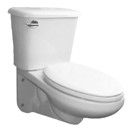
Wall Hung Back Outlet
Gravity Tank
PF1705 / 1710 /
PF1705HE / PF1710HE
CAUTION
5
Note: The back-up nuts, also referred to as the
PRODUCT IS FRAGILE
bearing nuts, must be set to take the full loading
Handle with care to avoid
from the fixture while allowing a 1/6" clearance
breakage and possible injury
between the fixture and the finished wall.
Follow the carrier manufacturer's recommendation
(A) Regular Screwdriver
settings for the outlet connection.
(B) Adjustable Wrench
A
(C) Marker
For installations where consideration
(D) Tape Measure
When setting fixture onto the carrier, it is not
(E) Level
recommended to use a wax ring, felt or neoprene
is given for ADA compliance, the seat
(F) Silicone Sealant
are recommended.
height must be 17" to 19" (432mm
(G) Putty Knife
(H) Flexible Supply Tube (Not Included)
483mm) from the finished floor.
(I) Closet Carrier/Support (Not Included)
When setting the fixture to the carrier, the waste
CAUTION: PRODUCT IS FRAGILE
gasket must be compressed sufficiently to assure
Handle with care to avoid breakage and possible injury!
a positive gas and watertight seal.
Installation
For installations where consideration is given for
ADA compliance, the seat height must be 17" to
7
Install the fiber washer and cap nut onto the mounting
19" (432 to 483) from the finished floor.
1. For typical installation of the wall hung back outlet fixture, a
stud #2, hand tighten until the nut and washer are
4-bolt Carrier/Support system, (not supplied with this unit)
Wall Hung Back Outlet Toilet with Tank Installation
SINK INSTALLATION:
touching the china. Hand snug firmly the cap nut against
must be used for attaching the water closet to the carrier/
the china, this is all that is necessary for mounting the
1
support system and waste drain. Refer to the Installation
For typical installation of the wall hung back outlet fixture, a
4-bolt Carrier/Support system, (not supplied with this unit)
cap nut and washer to stud #2.
Instructions that were supplied with the Closet Carrier/
must be used for attaching the water closet to the carrier/support
Support System for installation of the unit.
.
system and waste drain. Refer to the Installation Instructions
Caulk sealant into the gap between the toilet and the
that were supplied with the Closet Carrier/Support System for
Tools & Materials
installation of the unit.
finished wall.
9" (228mm)
G
E
I
H
F
Note: If you wrench tighten the cap nut on mounting
ble injury!
Note: Views in this illustrations are for general representation
stud #2 you will break the china since there is no
and may not necessarily define the exact contours of the product.
back nut on this stud.
If replacing an existing toilet be certain to shut off
Front View
water supply before removing old toilet.
9
3
2. If you are installing the toilet on an existing support system,
lation
Mounting studs should extend 2-1/8" (54mm) beyond the
Fit the tapered side of the large rubber gasket into the
finished wall.
make sure the system is in compliance with local code
inlet opening of the bowl. The tank should sit level and
2
If you are installing the toilet on an existing support system,
requirements and the support system is weight rated for
parallel to the finished wall.
The waste horn should extend 5/16" (8mm) beyond the
make sure the system is in compliance with local code
the application requirements.
finished wall.
pport
requirements and the support system is weight rated for
s
the application requirements.
Place the small rubber gaskets onto the tank mounting
r
bolts that were supplied with your tank. Slide both bolts
into the mounting holes from inside the tank.
Secure the tank by placing the metal washer and nut
onto the bottom of the tank bolts and tighten by hand
both nuts while holding the tank level.
Top View of Carrier
Finished Wall
With the tank level and sitting parallel to the wall, begin
2-1/8"
(54mm)
to tight the nuts alternating between the two nuts to
Cut Away of Mounting Hardware
keep the tank even. Tighten the nuts until the tank is
4
e
Place back up nuts supplied with the carrier/support on mounting
snug against the sanitary tank bar on the bowl.
stud #1, #3 and #4. No back-up nut is used on mounting
stud #2! Adjust the two lower back-up nuts so the front face of
the nuts are 1/16" away from the finished wall. Using a level,
CAUTION: PRODUCT IS FRAGILE
adjust the back-up nut on mounting stud #1 to a vertical plane
Do not over tighten nuts more than a snug fit.
with mounting stud #3. Place back-up washer on the three
installed back-up nuts.
© 2014 Ferguson Enterprises, Inc.
Note; If the wall is irregular, the three back-up nuts and
When performance matters.
washers must be positioned to allow a minimum of 1/16"
gap between the fixture and the wall.
(H) Flexible Supply Tube (Not Included)
(I) Closet Carrier/Support (Not Included)
SINK INSTALLATION:
1
3. Mounting studs should extend 2-1/8" (54mm) beyond the
3
finished wall. The waste horn should extend 5/16" (8mm)
beyond the finished wall.
Recommended Tools & Materials
E
B
C
4. Place back up nuts supplied with the carrier/support on
F
mounting stud #1, #3 and #4. No back-up nut is used on
D
mounting stud #2! Adjust the two lower back-up nuts so
the front face of the nuts are 1/16" away from the finished
wall. Using a level, adjust the back-up nut on mounting
stud #1 to a vertical plane with mounting stud #3. Place
back-up washer on the three installed back-up nuts.
Note: If wall is irregular, the three back-up nuts and
washers must be positioned to allow a minimum of 1/16"
2
gap between the fixture and the wall.
When performance matters.
5. Note: The back-up nuts, also referred to as the bearing
nuts, must be set to take the full loading from the fixture
while allowing a 1/6" clearance between the fixture
4
and the finished wall. Follow the carrier manufacturer's
recommendation settings for the outlet connection. When
setting fixture onto the carrier, it is not recommended to
use a wax ring, felt or neoprene are recommended. When
setting the fixture to the carrier, the waste gasket must
be compressed sufficiently to assure a positive gas and
watertight seal.
Mounting
Studs
6. Using two people, install the bowl onto the fixture mounting
studs. Place the fiber washer supplied with the carrier/
Back-Up Nut
support on mounting studs #1, #3 and #4. (Do not place
Back-Up
Washer
a fiber washer or cap nut on mounting stud #2 at this
Fiber
time.) Place the cap nut supplied with the carrier/support
Washer
on mounting studs #1, #3 and #4. While holding the bowl
Cap Nut
level and using an adjustable wrench, tighten the three cap
5/16"
nuts until they are snug. CAUTION: PRODUCT IS FRAGILE
(8mm)
Distributed Exclusively by Ferguson and Wolseley Canada
-1-
CAUTION: PRODUCT IS FRAGILE
Handle with care to avoid breakage and possible injury!
For installations where consideration is given for
ADA compliance, the seat height must be 17" to
19" (432 to 483) from the finished floor.
Wall Hung Back Outlet Toilet with Tank Installation
For typical installation of the wall hung back outlet fixture, a
4-bolt Carrier/Support system, (not supplied with this unit)
must be used for attaching the water closet to the carrier/support
system and waste drain. Refer to the Installation Instructions
that were supplied with the Closet Carrier/Support System for
installation of the unit.
9" (228mm)
Front View
Mounting studs should extend 2-1/8" (54mm) beyond the
finished wall.
6
Using two people, install the bowl onto the fixture mounting
The waste horn should extend 5/16" (8mm) beyond the
finished wall.
studs.
Place the fiber washer supplied with the carrier/support on
mounting studs #1, #3 and #4. (Do not place a fiber
washer or cap nut on mounting stud #2 at this time.)
Place the cap nut supplied with the carrier/support on
Finished Wall
mounting studs #1, #3 and #4. While holding the bowl
G
2-1/8"
I
(54mm)
level and using an adjustable wrench, tighten the three
5/16"
(8mm)
cap nuts until they are snug.
H
CAUTION: PRODUCT IS FRAGILE
Do not over tighten nuts more than a snug fit.
Note: Views in this illustrations are for general representation
When performance matters.
and may not necessarily define the exact contours of the product.
If replacing an existing toilet be certain to shut off
8
With the tapered side of the large rubber gasket facing
water supply before removing old toilet.
away from the tank, slip the rubber gasket over the
thread of the flushvalve on the bottom of the tank.
If you are installing the toilet on an existing support system,
Connect the flexible water supply tube (Not Included)
make sure the system is in compliance with local code
requirements and the support system is weight rated for
onto the fill valve of the tank.
the application requirements.
Set the tank onto the bowl,
with the tapered side of the
large rubber gasket towards
the bowl. While lowering the
tank onto the bowl, route
the flexible supply tube
through the opening provided.
Top View of Carrier
Cut Away of Mounting Hardware
10
Connect the flexible water supply line from the tank to
Place back up nuts supplied with the carrier/support on mounting
the shutoff valve. Tighten all coupling nuts securely.
stud #1, #3 and #4. No back-up nut is used on mounting
stud #2! Adjust the two lower back-up nuts so the front face of
the nuts are 1/16" away from the finished wall. Using a level,
Turn on water at the supply valve and allow the tank to fill.
adjust the back-up nut on mounting stud #1 to a vertical plane
with mounting stud #3. Place back-up washer on the three
installed back-up nuts.
Check all fittings for leakage and tighten any fittings that
Note; If the wall is irregular, the three back-up nuts and
washers must be positioned to allow a minimum of 1/16"
are leaking.
gap between the fixture and the wall.
Mounting Studs #1
Waste Drain
Mounting Studs #3
WARNING: Do not use plumbers putty, pipe dope or any other sealant on the
F
D
Note: Views in this illustrations are for general representation
and may not necessarily define the exact contours of the product.
If replacing an existing toilet be certain to shut off
water supply before removing old toilet.
5
2
Note: The back-up nuts, also referred to as the
If you are installing the toilet on an existing support system,
make sure the system is in compliance with local code
bearing nuts, must be set to take the full loading
requirements and the support system is weight rated for
from the fixture while allowing a 1/6" clearance
the application requirements.
between the fixture and the finished wall.
Follow the carrier manufacturer's recommendation
settings for the outlet connection.
When setting fixture onto the carrier, it is not
Top View of Carrier
recommended to use a wax ring, felt or neoprene
are recommended.
When setting the fixture to the carrier, the waste
Do not over tighten nuts more than a snug fit.
4
Place back up nuts supplied with the carrier/support on mounting
gasket must be compressed sufficiently to assure
7. Install the fiber washer and cap nut onto the mounting stud
stud #1, #3 and #4. No back-up nut is used on mounting
a positive gas and watertight seal.
stud #2! Adjust the two lower back-up nuts so the front face of
#2, hand tighten until the nut and washer are touching
the nuts are 1/16" away from the finished wall. Using a level,
the china. Hand snug firmly the cap nut against the china,
adjust the back-up nut on mounting stud #1 to a vertical plane
with mounting stud #3. Place back-up washer on the three
this is all that is necessary for mounting the cap nut and
7
Install the fiber washer and cap nut onto the mounting
installed back-up nuts.
washer to stud #2. Caulk sealant into the gap between the
Note; If the wall is irregular, the three back-up nuts and
stud #2, hand tighten until the nut and washer are
washers must be positioned to allow a minimum of 1/16"
toilet and the finished wall.
gap between the fixture and the wall.
touching the china. Hand snug firmly the cap nut agains
the china, this is all that is necessary for mounting the
Note: If you wrench tighten the cap nut on mounting stud
cap nut and washer to stud #2.
Mounting Studs #1
#2 you will break the china since there is no back nut on
.
this stud.
When performance matters.
Caulk sealant into the gap between the toilet and the
finished wall.
Mounting Studs #3
-1-
Note: If you wrench tighten the cap nut on mounting
8. With the tapered side of the large rubber gasket facing
stud #2 you will break the china since there is no
away from the tank, slip the rubber gasket over the thread
back nut on this stud.
of the flush valve on the bottom of the tank. Connect the
9
flexible water supply tube (Not Included) onto the fill valve
Fit the tapered side of the large rubber gasket into the
of the tank. Set the tank onto the bowl, with the tapered
inlet opening of the bowl. The tank should sit level and
side of the large rubber gasket towards the bowl. While
parallel to the finished wall.
lowering the tank onto the bowl, route the flexible supply
tube through the opening provided.
Place the small rubber gaskets onto the tank mounting
bolts that were supplied with your tank. Slide both bolts
into the mounting holes from inside the tank.
Mounting
Secure the tank by placing the metal washer and nut
Water
Studs
Supply
onto the bottom of the tank bolts and tighten by hand
Back-Up Nut
Opening
both nuts while holding the tank level.
Back-Up
Washer
Tank
With the tank level and sitting parallel to the wall, begin
Fiber
Washers
Washer
to tight the nuts alternating between the two nuts to
Cap Nut
keep the tank even. Tighten the nuts until the tank is
snug against the sanitary tank bar on the bowl.
9. Fit the tapered side of the large rubber gasket into the
inlet opening of the bowl. Place the small rubber gaskets
CAUTION: PRODUCT IS FRAGILE
onto the tank mounting bolts that were supplied with your
Do not over tighten nuts more than a snug fit.
tank. Place the metal washer and nut onto the bottom of
the tank bolts and tighten the nuts until the tank is snug
against the sanitary tank bar on the bowl.Connect the
supply line from the tank to the shutoff valve and tighten
all coupling nuts securely. Turn on water supply and allow
the tank to fill. Check for leaks and tighten fittings as
necessary.
Finished Wall View
Mounting Studs #2
Note: Views in this illustration are for general representation
and may not necessarily define the exact contours of the
product.
When performance matters.
Mounting Studs #4
7730/7730HE
REV 10/2013
®
Mounting
Studs
Back-Up Nut
Back-Up
Washer
Fiber
Washer
Cap Nut
Cut Away of Mounting Hardware
Finished Wall View
Mounting Studs #2
Waste Drain
Mounting Studs #4
7730/7730HE
REV 10/2013
Tank
Bolts
Rubber
Gasket
Tank Nuts
18218 04/14
Advertisement
Table of Contents

Related Manuals for ProFlo PF1710


Summary of Contents for ProFlo PF1710
- Page 1 (H) Flexible Supply Tube (Not Included) (I) Closet Carrier/Support (Not Included) CAUTION: PRODUCT IS FRAGILE Installation Instructions Handle with care to avoid breakage and possible injury! Note: Views in this illustrations are for general representation and may not necessarily define the exact contours of the product. For installations where consideration is given for ADA compliance, the seat height must be 17”...
- Page 2 Troubleshooting Troubleshooting Wall Hung Back Outlet Wall Hung Back Outlet ® Gravity Tank Gravity Tank PF1705 / 1710 / PF1705HE / PF1710HE PF1705 / 1710 Difficulties These parts must be used as illustrated to ensure a water tight connection Difficulties Reason Solution METAL/COPPER...
- Page 3 CAUTION: PRODUCT IS FRAGILE Handle with care to avoid breakage and possible injury! Note: Views in this illustrations are for general representation and may not necessarily define the exact contours of the product. For installations where consideration is given for Instructions d’installation ADA compliance, the seat height must be 17”...
- Page 4 Dépannage Dépannage Réservoir de gravité Réservoir de gravité à ® à sortie arrière de type mural sortie arrière de type mural PF1705 / 1710 / PF1705HE / PF1710HE PF1705 / 1710 Dépannage Difficultés Raisons Solution Ces pièces doivent être utilisées telles qu’illustrées pour assurer une connexion d’eau étanche. Le robinet de MÉTAL/CUIVRE À...
- Page 5 CAUTION: PRODUCT IS FRAGILE Handle with care to avoid breakage and possible injury! Note: Views in this illustrations are for general representation Instrucciones de instalación and may not necessarily define the exact contours of the product. For installations where consideration is given for ADA compliance, the seat height must be 17”...
- Page 6 Solucion de problemas Solución de problemas Tanque de gravedad de descarga Tanque de gravedad de descarga ® trasera para colgar en pared trasera para colgar en pared PF1705 / 1710 / PF1705 / 1710 PF1705HE / PF1710HE Solución de problemas Estas partes deben usarse conforme se ilustra para garantizar una conexión de sellado hermético Dificultades Razones...
Need help?
Do you have a question about the PF1710 and is the answer not in the manual?
Questions and answers