Table of Contents
Advertisement
Quick Links
Download this manual
See also:
Installation Manual
Advertisement
Table of Contents

Subscribe to Our Youtube Channel
Related Manuals for Zehnder Rittling ComfoControl Luxe


Summary of Contents for Zehnder Rittling ComfoControl Luxe
- Page 1 ComfoControl Luxe Handleiding Manual Manuel Anleitung...
-
Page 2: Table Of Contents
Table of Contents 1 INTRODUCTION ................................................................ 1.1 Foreword ............................................................................. 1.2 Warranty and liability ..................................................................1.2.1 General ......................................................................... 1.2.2 Warranty conditions ................................................................ 1.2.3 Liability ........................................................................1.3 Safety instructions ....................................................................1.3.1 Pictograms used ................................................................... 2 FOR THE USER ................................................................2.1 ComfoControl ........................................................................2.2 Using ComfoControl .................................................................... -
Page 3: Introduction
Introduction • Non-compliance with the safety, set-up and operating instructions in this manual. This chapter provides general information on the ComfoControl. • The use of components not supplied or recommended by the manufacturer. • Responsibility for the use of such components lies en- 1.1. -
Page 4: Comfocontrol
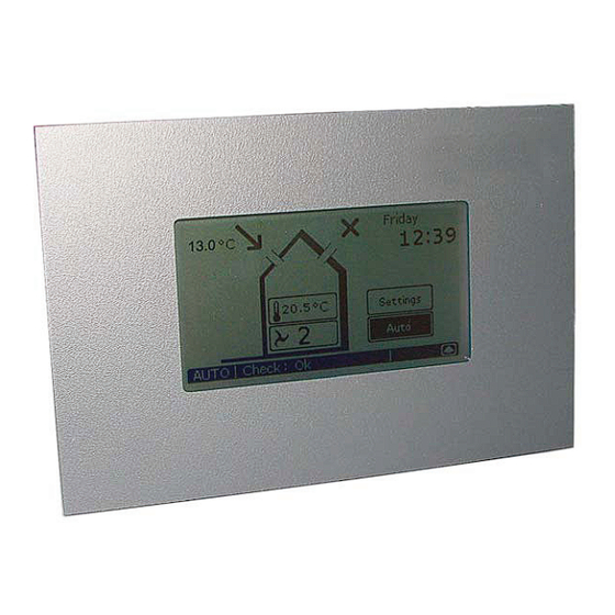
ComfoControl The ComfoControl regulates your ventilation and/or cooling system. • The ComfoControl is mounted to the living room wall and communicates with your ventilation and/or cooling system. The list below briefl y explains what information the unit displays. The ComfoControl display is a touch screen. All settings can be accessed, adjusted and confi rmed simply by touching the screen. If the function is not Cooling system, If the function is not... -
Page 5: Comfort Temperature Settings
2.2.2 Comfort temperature settings The procedure is as follows: 1. Press "COMFORT TEMPERATURE", currently " ". • Active cooling can be deactivated. In the screen in which the comfort temperature can be entered, you will see a button that can be set to either “Artic Auto” or “Artic Off”. -
Page 6: Switching Extractor Hood On/Off
- Use for cooking, showering and if • “ ” for extractor hood ventilation setting 1. extra ventilation is required. The ComfoControl will display " " as stand- • “ ” for extractor hood ventilation setting 2. ard during manual ventilation, and not " ". -
Page 7: Ventilation Programme Settings
Bear in mind that switching off the supply or ex- haust fan will temporarily immobilize your bal- anced ventilation system. Once the supply or exhaust fan has been deac- tivated, “ ” will no longer be displayed, but “ ” will appear on the ComfoControl as standard. -
Page 8: Temperature Programme Settings
main screen. The programmed ventilation level only works in the AUTO setting. After 30 seconds, the ComfoControl will return to the main menu automatically. Your settings have now been saved. 2.2.7 Temperature programme settings Use the ComfoControl to: • Set a personal temperature programme. The ComfoControl comes with default temperature set- tings. -
Page 9: Time Delay Settings
2.2.8 Time delay settings The programmed temperature level only works Use the ComfoControl to: in the AUTO setting. • Programme a time delay for certain ventilation set- tings. After 30 seconds, the ComfoControl will return to The procedure is as follows: the main menu automatically. -
Page 10: Screen Settings
2. Press “ ”. 3. Press “ ” and then “ ”. 5. Press “ ” or “ ” to set the number of minutes (weeks) delay required. 6. Press “ ” to confi rm the settings and return to the 4. -
Page 11: Language Settings
3. For “ ” press “ ” or “ ” to adjust the clar- After 30 seconds, the ComfoControl will return to BRIGHTNESS ity. the main menu automatically. Your settings have now been saved. 2.3 System data Certain system information can be displayed on the Com- foControl: –... -
Page 12: End Of Useful Life
ventilation and/or cooling system for long periods. 2.3.2 ComfoControl fi lter warning If the ventilation system’s fi lters require replacement (or cleaning), then the “FILTERS – REPLACE FILTERS” warn- ing appears on the ComfoControl display. To replace (or clean) any fi lters, please refer to your ventilation system’s user manual. -
Page 13: Wall Mounting
Wall mounting 3.5 Connection to external • Mount the bracket on the wall. temperature sensor • Connect the temperature sensor cable to the connec- tor. The wiring diagram can be found at the rear of the Com- foControl: Plug the connector into the “TEMP.SENS” fi tting on •... - Page 14 3. Press “ ”; and then “ ”. 8. Press “OK” to confi rm the P menu selected. 9. Using “ ” or “ ” , select the required P sub- menu, e.g. “P51 PRE HEATER”. 4. Press code “3520” to go to the “INSTALLATION MENU”.
- Page 15 After fi ve minutes, the ComfoControl will return 13. If necessary, press “ ” again to return to the P automatically to the main screen. menus. Once parameters have been set in the P menus, the ComfoControl returns almost immediately to the main screen.
Need help?
Do you have a question about the ComfoControl Luxe and is the answer not in the manual?
Questions and answers