Advertisement
Advertisement
Table of Contents

Related Manuals for Maxima ML4030B

Summary of Contents for Maxima ML4030B
- Page 1 MAXIMA HEAVY DUTY COLUMN LIFT ML4030B/ML6045B USER MANUAL...
-
Page 2: Table Of Contents
CONTENT 1. Cautions ......................- 1 - 2. Features......................- 3 - 3. Technical Parameter ..................- 3 - 4. Structure sketch....................- 4 - 5. The Electronics ....................- 5 - 6. Debugging ......................- 8 - 7. Operation ....................... - 10 - 8. -
Page 3: Cautions
1.4 Load type of electric motor is S2, with 15 minutes working time; 1.5 Maxima Heavy Duty Column Lift is equipped with double safety system of mechanical lock and hydraulic check valve. Before working under elevated vehicle, please make sure there is no abnormality with all connections;... - Page 4 MAXIMA Safety Instruction Warning Caution It is necessary to refer to complete The field of motion of the load and of the operation instructions, especially Never overload lift load carrying devices shall be free of trouble shooting.The operation of the lift obstructions is permitted by authorized persons only.
-
Page 5: Features
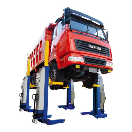
High accuracy balancing system ensures the cylinders working synchronously. Unique design fits heavy duty vehicle assembling and repair shop. ML4030B/ML604B applies to vehicles within 30/45 tons for purposes of assembly, repair, and maintenance, oil-changing, washing and other possible services. -
Page 6: Structure Sketch
4. Structure sketch Dustproof cover Big Cover Connector Column Charger door Hydraulic trolley Carriage Adjustable fork arm Fig. 2 - 4 -... -
Page 7: The Electronics
5. The Electronics The electric control system of ML4030B/ML6045B includes: one master and three slave control boxes (ML4030B), or five slave control boxes (ML6045B). Each column has one displacement sensor, one electric hydraulic pump, one microswitch, and one electromagnet. - 5 -... - Page 8 “FAULT” light POWER light Emergency button Connector Connector Mode selection knob “UP” button Power Switch “DOWN” button Fig. 4 Master Control Box POWER light “FAULT” light Emergency button Connector Connector “UP” button Power Switch “DOWN” button Fig. 5 Slave Control Box - 6 -...
- Page 9 Safety Hook Micro-Switch Electromagnet Fig. 6 Slave Control Box 5.1. Control switches 5.1.1. Power switch When this switch is at “OFF”, the lift is powered off and no operation is available; when this switch is at “ON”, the lift is powered on and prepared for operation. Switch to “CHARGE” to charge the battery.
-
Page 10: Debugging
5.1.5. Emergency button When you press this switch, no operation is available immediately. There is one emergency button on each control box. It must be released before lift operation. Then turn on the power switch. 5.1.6. Operation button “UP” button: Press and hold this button, the carriages will rise. “DOWN”... - Page 11 Press endure: Press and hold the “UP” button, the carriage rises to its highest position. After holding 5 seconds, check and make sure there’s no hydraulic oil leaking out. Lower: Press and hold the “DOWN” button, the carriages go down to the required height after the safety hooks unlocked automatically.
-
Page 12: Operation
7. Operation We introduce four columns operate process here; operation of two columns is the same way. 7.1. Raise 7.1.1. After testing successfully, move the four holding fork arms to their very positions. The contacting range must equal with the width of the tires. The right position of each column is shown as Fig.11. -
Page 13: Hydraulic Trolley
8. Hydraulic Trolley 8.1. Lifting Put down the handlebar, press it up & down several times, in order to lift the column at 30 ~ 40mm height from the ground. Refer to Fig. 13, 14. Lifting bracket hydraulic trolley handlebar Fig. -
Page 14: Addendum 1: Hydraulic Valve
Addendum 1: Hydraulic valve - 12 -... -
Page 15: Addendum 2: Transportation Indications
Addendum 2: Transportation Indications Serial number : Plac ed and Sc oop up direc tion: Forbidden falling dow n! Trans it :Ex c ept the beam and the bottom of the c olum n , Forbidden pac k ing and s us pending any other part ! 横...
Need help?
Do you have a question about the ML4030B and is the answer not in the manual?
Questions and answers