
Related Manuals for Maxima ML-6045BC

Summary of Contents for Maxima ML-6045BC
- Page 1 MOBILE COLUMN LIFT ML-4030BC ML-6045BC ML-4034BC ML-6051BC Installation, Operation, Maintenance Manual IMPORTANT: READ THIS MANUAL COMPLETELY BEFORE INSTALLING OR OPERATING YOUR LIFT MIT Automobile Inc. 1151 West 5 Street Azusa, California 91702...
-
Page 2: Important Safety Instructions
OWNER / EMPLOYER OBLIGATIONS The Owner/Employer shall ensure that lift operators are qualified and that they are trained in the safe use and operation of the lift using the manufacturer’s operating instructions; ALI/SM10-1, ALI Lifting it Right safety manual; ALI/ST-10 ALI Safety Tips card; ANSI/ALI ALOIM-2008, American National Standard for Automotive Lifts - Safety Requirements for Operation, Inspection and Maintenance;... - Page 3 in contact with hot manifolds or moving fan blades. 5. If an extension cord is necessary, a cord with a current rating equal to or more than that of the equipment should be used. Cords rated for less current than the equipment may overheat.
- Page 4 WARNING! Failure by purchaser to provide the recommended mounting surface could result in unsatisfactory lift performance, property damage, or personal injury. LOCATION This lift has been evaluated for indoor use only with an operating ambient temp. range of 5 - 40°C (41-104°F) For additional safety instructions regarding lifting, lift types, warning labels, preparing to lift, vehicle spotting, vehicle lifting, maintaining load stability, emergency procedures, vehicle lowering, lift limitations, lift maintenance, good shop practices, installation, operator training...
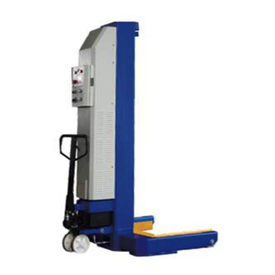
- Page 5 REFERENCE: AUTOMOTIVE LIFT INSTITUTE SAVE THESE INSTRUCTIONS Note: Some images in this manual are generic and may not resemble the lift you have purchased.
-
Page 6: Specifications
Two (2) spare hydraulic fittings. Two (2) keys for column door interlock Important document packet that includes, Maxima Installation, Operation and Maintenance Manual, ALI Manual, “Lifting it Right”, Automotive Lift Safety Tips Placard, ALI “Lifting Points Guide”, ANSI/ALI ALOIM:2008 Safety Requirements for Operation, Inspection and Maintenance. -
Page 7: Installation Instructions
5. Clean new * AW-32 Hydraulic Oil Hydraulic Oil needed per model ML-4030BC 13 Gallons / 49.2 Liters ML-6045BC 19.5 Gallons / 73.8 Liters ML-4034BC 15 Gallons / 56.8 Liters ML-6051BC 22.5 Gallons / 85.2 Liters *Note: Use only new fresh clean AW-32 Hydraulic Oil. - Page 8 (AW-32) to the tank and fill to approx. 2” from the top of the tank fill hole. The approx. amount of oil per column is shown below: ML-4030BC 13 Quarts / 12.3 Liters ML-6045BC 13 Quarts / 12.3 Liters ML-4034BC 15 Quarts / 14.3 Liters ML-6051BC 15 Quarts / 14.3 Liters Install the black breather cap in the top of the tank.
- Page 9 removing the bolt and then pull outward on the black knob and fully open the door. A battery charger is built in to each column. Plug the battery charger electrical cord into a 110 volt grounded electrical outlet. Charge each mobile column lifts using a separate electrical outlet. Best performance will be obtained by charging all mobile column batteries at the same time.
- Page 10 The electronic control system of ML-4030BC and ML-4034BC includes one master and three slave control panels. The electronic control system of the ML-6045BC and ML6051BC includes one master and five slave control panels. Each column has one displacement sensor, one electric hydraulic pump, one micro-switch, and one electromagnet.
- Page 11 FAULT light POWER light Emergency button Connector Connector “UP” button “LOCK” button “DOWN” button Slave Control Panel Control switches: Power switch: (located on the right side of each column) when this switch is at “OFF”, the lift is powered off and no operation is available; when this switch is at “ON”, the lift is powered on and prepared for operation.
- Page 12 In case of an emergency, use the key to access the control panel and move the switch to right side as illustrated below so that the equipment can be operated without the communication cables connected. The switch is located at the extreme lower left side of the circuit board next to the fuse holder.
- Page 13 Operation test: Power on: Connect all 4/6 columns with communication cables as shown above, turn the Mode Selection knob to SINGLE, and power on main column and all slave columns. LCD screen will show work interface after successful connection. Rise: Unloaded, press and hold the “UP” button on the master control box, check if the carriage rises normally.
- Page 14 Lifting Vehicles: 1. Check and correct the tire pressure in each tire. 2. Position each mobile column adjacent to each tire on the vehicle. If the vehicle has dual rear axles position the mobile columns to use on the drive axle. Note: If an older vehicle has air bag suspension on the non-drive axles and mobile column are not used, extra support for the axles may be needed to prevent air bag damage.
-
Page 15: Maintenance Instructions
11. To move the vehicle, turn off the power at all lift columns and disconnect the communication cables. Move the mobile columns safely away from the vehicle before attempting to move the vehicle. Use caution to not drive over the communication cables. Maintenance Instructions Caution: If you are not familiar with vehicle lift maintenance and service procedures, do not... - Page 16 Error Code 5-X: Check for overheated power unit. The control panel has power unit cycle times posted. If these times are exceeded the power may overheat. If this occurs allow the power unit to cool off to the recommended duty cycle time Error Code 6: “UP”...
- Page 17 Responsibility The responsibility for assuring that this procedure is followed is binding upon all employees and service personnel from outside service companies (Installers, contactors, service repairmen). All employees shall be instructed in the safety significance of the lockout procedure by the facility owner/manager.
- Page 18 Lift Parts and Drawings ML-4030BC/ML-6045BC Mechanical Parts List ITEM DESCRIPTION CODING ITEM DESCRIPTION CODING 2030048-0011 2030014-0040 Column Big Cover 2030047-1000 2030014-0041 Reinforce Bracket Battery Fixing Frame 1150009-0025 2030014-0043 Bumper p Battery Seat 1040018-0003 2020010-0194 Torsion spring Battery Fixing Strip 2040009-1000...
- Page 19 2040008-1008 800201457 Swing Block Plug 2020008-1016 500206414227 Slider Block Resv,Plastic,9*10*18 2030067-0001 50020852019603 Holding Fork Arm Pressure Relief Valve 2050034-1002 1140004-0254 Hydraulic Dolly Active Fitting NPT3/8 2040063-0002 1140004-0035 Left Crank Right-angle Fitting NPT3/8 2040063-0003 500216101723100 Right Crank Little Poppet Assy 2040002-0206 500216101723200 Support shaft Big Poppet Assy...
- Page 21 ML-4030BC/ML-6045BC /ML-4034BC/ML-6051BC Electric Parts List ITEM DESCRIPTION CODING ITEM DESCRIPTION CODING 2040029-0108 1130004-0077 Fault Light Master Control Box Door 2040029-0109 1130004-0075 Slave Control Box Door E-Stop 1150009-0021 2060002-0064 Control Board Seal Strip 2040084-0001 1130012-0084 Wiring duct-slot Main Board Fixing Pedestal...
- Page 23 ML-4034BC/ML-6051BC Mechanical Parts List ITEM DESCRIPTION CODING ITEM DESCRIPTION CODING 2030048-0012 2030014-0040 Column Big Cover 2030047-1000 2030014-0041 Reinforce Bracket Battery Fixing Frame 1150009-0025 2030014-0043 Bumper Up Battery Seat 1040018-0003 2020010-0194 Torsion spring Battery Fixing Strip 2040009-1000 2030051-0001 Safety Hook Fixing Bracket Hook shaft 2040002-1000 2020002-0153...
- Page 24 2040005-1034 800500967 Shaft Sheath Base Valve Block 2040008-1008 800201457 Swing Block Plug 2020008-1106 500206414227 Resv,Plastic,9*10*18 Slider Block 2030067-0001 50020852019603 Holding Fork Arm Pressure Relief Valve 2050034-1002 1140004-0254 Hydraulic Dolly Active Fitting NPT3/8 2040063-0002 Right-angle Fitting NPT3/8 1140004-0035 Left Crank 2040063-0003 500216101723100 Right Crank Little Poppet Assy...
- Page 26 ML-4030BC/ML-6045BC /ML-4034BC/ML-6051BC Electric Parts List ITEM DESCRIPTION CODING ITEM DESCRIPTION CODING 2040029-0108 1130004-0077 Fault Light Master Control Box Door 2040029-0109 1130004-0075 Slave Control Box Door E-Stop 1150009-0021 2060002-0064 Control Board Seal Strip 2040084-0001 1130012-0084 Wiring duct-slot Main Board Fixing Pedestal...
- Page 27 Maxima A Division of MIT Automobile Inc. 1151 West 5 Street Azusa, California 91702 626-774-5700...
Need help?
Do you have a question about the ML-6045BC and is the answer not in the manual?
Questions and answers