Table of Contents
Advertisement
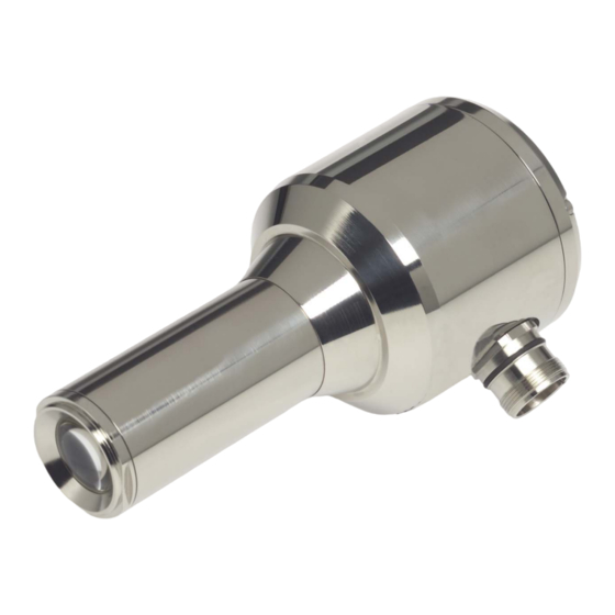
Technical documentation
•
Compact casing with integrated flame
sensor and switching amplifier
•
Sensitivity adjustment in multiple steps
•
Digital circuit design for flame evaltion
•
LED status indicator
Sensors and systems
for industrial flame monitoring
F 200 K Compact flame detector
•
24 V DC operating voltage
•
Dual-channel system with electronic self-
monitoring
•
LED bar flame intensity indicator and
4 (0) ... 20 mA measuring output
•
Selectable trend indicator allowing opti-
mum adjustment to the flame direction
Advertisement
Table of Contents
Troubleshooting

Subscribe to Our Youtube Channel
Related Manuals for Lamtec F 200 K

Summary of Contents for Lamtec F 200 K
- Page 1 Technical documentation F 200 K Compact flame detector • Compact casing with integrated flame sensor and switching amplifier • Sensitivity adjustment in multiple steps • Digital circuit design for flame evaltion • LED status indicator • 24 V DC operating voltage •...
-
Page 2: Table Of Contents
Table of Contents General remarks ......................4 Allow for compliance with the Equipment Safety Act ................. 4 Safety instructions ......................5 Operating instructions ....................6 Application ..............................6 Purpose intended ............................6 Design................................. 6 Mode of operation............................7 Basic circuit diagram ..........................8 Technical parameters....................9 Characteristics............................ - Page 3 F 200 K2 … (Ex-proof), (in the state as delivered) .................. 25 Dimensional drawings ....................26 10.1 F 200 K … and F 200 K Compact Flame Detectors... Z2 (hazardous area II)......... 26 10.2 F 200 K2 … Compact Flame Detector Ex (hazardous area I) ..............27 10.3...
-
Page 4: General Remarks
LAMTEC GmbH & Co KG shall not be held liable for any damage caused by non- compliance with the instructions given in this manual. The warranty and liability condi- tions of LAMTEC GmbH &... -
Page 5: Safety Instructions
Safety instructions This operator manual uses the following symbols to mark important safety instructions to be complied with by the user. In the following sections, this symbols appear in texts at places where the information is required. Make sure to comply with these safety in- structions, in particular note the warnings. -
Page 6: Operating Instructions
Operating instructions Application These operating instruction apply to the F 200 K compact flame detector. The devices comply with the following standards and rules: DIN EN 230 DIN EN 298 DIN VDE 0116 97/23/EG (directive on pressurised equipment) 90/396/EWG (directive on gas equipment) -
Page 7: Mode Of Operation
The turning knob controls of the F 200 K1 / F 200 K2 compact flame detectors allow to set 6 to 12 sensitivity levels, the F 200 K version providing an increased sensitivity level in range II. A six-step green LED indicator indicates the evaluated flame intensity on the rear side of the device. -
Page 8: Basic Circuit Diagram
Basic circuit diagram Flame sensor Detector Switch-over contact Cycle 7...1 7...1 1...6 1...6 Channel A Channel B 10/20/30...190 Hz digital band pass 10/20/30...190 Hz digital band pass Sensitivity selector switch safe de-coupling safe de-coupling 0/4...20mA Intensity remote Visual intensity indicator indicator Switching amplifier Switching amplifier... -
Page 9: Technical Parameters
Technical parameters Characteristics The compact flame detector is available in 2 basic versions, apart from an ex-proof enclosure type with several spectral varieties (IR / UV). Design type F 200 K1... F 200 K2... (Ex) Sensitivity range 1 sensitivity range 2 sensitivity range 6 levels increased sensitivity in... - Page 10 - admissible switching current 0.5 A maximally 10 mA minimally, at a limit load of 50 mA - Switching capacity 0.1 W minimally 30 W maximally - Internal fuses, 500 mA slow IEC and/or 750 mA slow UL ≤ 1 s and/or ≤ 3 s, - Safety period "Operation"...
-
Page 11: Selection Criteria
Vibration fatigue limit according to EN 298, section. 6.5.2.2.2 function tested Protection type IP 67; in closed state Mass 0.6 kg Storage conditions (in original packing) Storage location closed premises Air temperature - 40 ... +70 °C Air humidity max. 80% at 35 °C Transport conditions (in original packing) Type of transport in closed holds... -
Page 12: Installation And Assembly Instructions
Installation and assembly instructions Assembly / Basic instructions The radiation emitted by a flame contains a pulsating portion (flickering). This results from the processes, which occur during combustion, the oscillation frequency (flame frequency) of which is used for monitoring. The compact flame detector is installed at the burner at the viewing port provided for this and using the appropriate adjustable holding device. -
Page 13: Installation
Installation 6.2.1 External installation Output contacts The flame detector ready for operation delivers the "Flame in" or "Flame out" status message to a floating output contact. Further signal processing has to be carried out by the controller adapted to the related furnace. To guarantee a high safety level make sure when installing the output contacts to lay out the circuitry of the radio interference suppression system to be provided by the user in such a manner as to avoid shorting-out of the contacts due to faulty compo-... -
Page 14: Instructions On Commissioning And Maintenance
Instructions on commissioning and maintenance Display and operational controls Represented in section 9 7.0.1 Intensity indicator including the “Adjust“ function / section 9.1 + 9.2, items 3 and 6 Intensity indication is effected by means of a roaming light dot in 6 levels. The indica- tion is delayed in accordance with switch-off time (1s and/or 3s) and fulfils 2 functions. -
Page 15: Sensitivity - Switch/ Sections 9.1 + 9.2, Items 4 And 5
7.0.4 Sensitivity – Switch/ sections 9.1 + 9.2, items 4 and 5 Depending on the solution type (F 200 K1 or F 200 K2), there are 1 or 2 sensitivity se- lector switches. The sensitivity selector switches can be set in 6 steps. The switches serve to adapt the device to the existing flame intensity. -
Page 16: Commissioning
1. Carry out the complete electrical installation of the flame detector and connect it to the supply voltage. A LAMTEC test emitter of the FFP 02 type (IR + UV) can be used as an auxiliary means for flame simulation. -
Page 17: Adjustment
UV light pass (e.g. quartz) without problems. They are al- ready contained in the LAMTEC-UV adjustable holding device (FS 19, FS 20, FV 19 and FV 20). Small accumulations of dust, water etc. are considerably more likely to lead to problems in flame detection than IR radiation. - Page 18 EN 61010-1 (safe insulation), and having a measuring resistance > 5 MΩ. The trigger threshold for the F 200 K is at ≥ 25 mV AC , while the measured sig- nal voltage can amount to maximally 3 V AC.
-
Page 19: Checking The Flame Shut-Down On Fault
This may chiefly be due to the in- terference emission of the ignition transformer during ignition. Check the shielding and FPE for proper connection to the F 200 K Carry out a proper grounding of the ignition transformer... -
Page 20: Faults During Ignition
7.1.6 Faults during ignition Faults occurring during ignition may have 4 causes. 1. In case of additionally monitoring the pilot flame, the pilot flame may not suffi- ciently be detected. Check the pilot flame for stable operation Check that the pilot flame is sufficiently visible within the viewing scope of the compact flame detector, and change pilot burner adjustment if required. - Page 21 Check the supply voltage Connect the flame detector to the supply voltage Check the supply voltage at the 1st clamping point behind the flame detector between the red and the blue connection wire for compliance with the voltage limits (in particular the lower limit) Repeat test with simulated flame If the supply voltage is too low, this may be due to excessive lengths of the supply lines which core sections are too small, apart from other faults.
-
Page 22: Commissioning Flow Chart
Commissioning flow chart Settings to be carried out before burner commissioning Check all electrical connections for presence and tight installation Verify cable laying, including continuous shielding and FPE connection Compact flame detector Check the compact flame detector for proper functioning (section 7.1.2) Orient the compact flame detector to the 1st third of the main flame or pilot flame to be monitored The flame must be visible throughout the operating range... -
Page 23: Maintenance
Delivery will comply with ordering details. The terms of deliveries and services of LAMTEC, and the general terms of delivery for products and services made or ren- dered by companies of the electrical industry, shall apply. -
Page 24: Layout Of The Operational Controls
- Service switch, according to section 7.0.6 / Adj.- Adjust, according to section 7.0.7 7/8 – Measuring points to measure the flame radiation received by the F 200 K according to section 7.1.3 9 – Start-up suppression, according to section 7.0.8 and 7.1.3... -
Page 25: 200 K2 ... (Ex-Proof), (In The State As Delivered)
Service switch, according to section 7.0.6 / Adj.- Adjust, according to section 7.0.7 / frequency switch according to section 7.0.5 7/8 – Measuring points to measure the flame radiation received by the F 200 K, according to section 7.1.3 9 –... -
Page 26: Dimensional Drawings
Dimensional drawings 10.1 F 200 K … and F 200 K Compact Flame Detectors... Z2 (hazardous area II) Ø Light entry port Purchase order numbers F 200 K … : Purchase order numbers F 200 K … Z2: F 200 K1 IR-1... -
Page 27: Connection Housing Fg 24 Ex
Surfac: Cylindrical pipe Thread withe aluminium RAL 9006 matt DIN ISO 228/1 Weight about 1,8 kg Purchase order numbers F 200 K … Ex: F 200 K2 IR-1 Ex 659 R 6102 F 200 K2 UV-1 Ex 659 R 6104... -
Page 28: Pin Configuration
Pin configuration 11.1 F 200 K1 … Connection cable F 200 K1 4(0)..20 mA without function 24 V FN 20 Connection cable F 200 K1 230V 4(0)..20 mA without function 24 V - white - weiß - pink - rosa - blue - blau - brown... - Page 29 11.2 F 200 K2 ... (Ex) Connection cable F 200 K2 4(0)..20 mA Range 24 V FN 20 Connection cabel F 200 K2 230V 4(0)..20 mA Range 24 V - white - weiß - pink - rosa - blue - blau - brown - braun - yellow...
-
Page 30: Examples Of Application
Examples of application 12.1 Interconnection with Etamatic Connection cable F 200 K1 Etamatic 24 +24V Flame signal 4(0)..20 mA without function 24 V +24V 12.2 Interconnection with FMS Connection cable F 200 K2 +24V Flame signal 4(0)..20 mA 56 Flame intensity Range 24 V +24V... -
Page 31: Accessories
13.1 FN 20 mains supply unit 13.1.1 Purpose The FN 20 mains supply unit is used to connect the F 200 K to a mains A.C. It has been designed for top hat rail installation (as an option, it is also available for plate mounting). - Page 32 Admissible switching current max. 0.5 A min. 10 mA, at a limit load of 50 mA Switching capacity min. 0.1 W on DC voltage max. 30 W on AC voltage max. 120 W ≤ 500 mA slow IEC, ≤ 750 mA slow UL External fuse Caution ! Output contact, safe <<...
-
Page 33: Pin Configuration
13.1.3 Pin configuration FN 20 Flame- contact Signalling- contact 4(0)..20 mA F 200 K Sensitivity 24 V selector Mains - white - weiß - pink - rosa - blue - blau - brown - braun - yellow - gelb - grey... - Page 34 Dimensioned drawing IP65 housing Purchase order no.: 659 R 6010/G Width 100 mm Length 160 mm Height 80 mm Weight 1.15 kg D4,8 0/4..20mA F 200 K Remote switch-over Mains Signal Safe contact contact - 34 -...
- Page 35 13.2 FWS 01 weather shield for F 200 K The weather shield is intended to chiefly protect the electronic parts in outdoor instal- lations, if the cover has to be opened for commissioning and repair services under in- clement weather conditions (rain, snow etc.). Moreover, the weather shield offers sun shade protection on sunny days to improve the visibility of the indicators.
-
Page 36: Adjustable Holding Devices
13.3 Adjustable holding devices 13.3.1 FS 19-10 (for IR and UV, without ball-and socket-joint, with purge air connection) Purchase order no.: 659 R 0102 ± 5 ± 2 1" 1" Insulating part ½" Compact- Fixing by means of flame sensor a camping ring / thumb nut 13.3.2 FS 20-10 (for IR and UV, with ball-and socket-joint and purge air connection) Purchase order no.: 659 R 0106... -
Page 37: Fv 19-10 (For Ir And Uv, Without Socket-And-Ball-Joint, With Purge Air Connection)
13.3.3 FV 19-10 (for IR and UV, without socket-and-ball-joint, with purge air connection) Purchase order no.: 659 R 0102/V ± 2 Stopper disk Joint not detachable detachable ± 2 Sealing ring Screwed connection detachable not detachable Counter hold SW 38 Screwed connection Ø... -
Page 38: Fs 50 (Without Ball-And-Socket-Joint And Cooling Air Housing)
View of the FV 20-10 with F 200 K Ex ±5 Ball-and-socket- ±5 Operating state joint ± 20° Stopper disk indicator in two levels detachable Sleeve nut SW 53 Cable entry not Thread G 1½ detachable Sensor connection Inner thread G ½"... -
Page 39: Fs 51 (With Ball-And-Socket Joint And Cooling Air Housing)
13.3.6 FS 51 (with ball-and-socket joint and cooling air housing) Purchase order no.: 659 R 6107 ca. 335 < 15 ca. 52 ca. 20 Insulated mounting Sealing ring position of flame sensor 56x42x2 (Galvanic isolation) (Lens cleaning) Detachable connection 8 Kt SW 66 Cabel connector with screwed View "A"... -
Page 40: Installation In The Cooling Air Housing
13.3 Installation in the cooling air housing F200K 56 x 42 x 2 80 x 2,5 22 x 3 hexagon 2,5 nylon M6 glass cleaned Rp 1/2 cooling air input Rp 1 F200K isolated build in - 40 -... -
Page 41: Eg Certificate Of Conformity
Manufacturer: LAMTEC Leipzig GmbH & Co KG Address: Schlesierstraße 55, 04299 Leipzig Product name: F 200 K ...Compact flame detector Product ID number: CE-0085BO0005 The product named above complies with the regulations of the following European directives: Number Text 90/396/EWG... -
Page 42: Ec Prototype Testing Certificate
EC Prototype testing certificate - 42 -... -
Page 43: 16 Tüv Certificate
TÜV Certificate - 43 -... - Page 44 GOST - Zertifikat - 46 -...
- Page 45 EG Baumusterprüfbescheinigung, Ex- Zone 1 - 47 -...
- Page 46 Baumusterprüfbescheinigung, Ex- Zone 2 - 48 -...
- Page 47 LAMTEC Meß- und Regeltechnik LAMTEC Leipzig GmbH & Co KG Handed over by: für Feuerungen GmbH & Co KG Impexstraße 5 Schlesierstraße 55 D-69190 Walldorf D-04299 Leipzig Phone (+49) 0 62 27 / 60 52-0 Phone (+49) 03 41 / 86 32 94 00...
Need help?
Do you have a question about the F 200 K and is the answer not in the manual?
Questions and answers