
Related Manuals for Lamtec F152

Summary of Contents for Lamtec F152
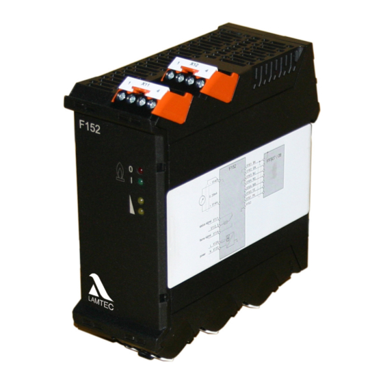
- Page 1 Manual Flame Monitoring Device F152 Sensors and Systems for Combustion Engineering www.lamtec.de...
-
Page 3: Table Of Contents
Table of Contents Table of Contents Important Information about the Manual ........4 Purpose/Applicability of the Document . - Page 4 11.2.1 F152 with FFS07/FFS08 ........
- Page 5 Important Information about the Manual Purpose/Applicability of the Document This manual allows you to use the LAMTEC Flame Monitor F152 in combination with the LAMTEC flame scanners FFS07 or FFS08 safely and efficiently. This manual is valid for all F152/FFS07/FFS08 in any configuration.
-
Page 6: Important Information About The Manual
Important Information about the Manual Target Group These instructions must have been read carefully and completely before commencing with any work. The basic prerequisite for working safely is compliance with all the specified safety instructions. NOTICE All assembly, commissioning, troubleshooting and maintenance work may only be carried out by authorised and trained personnel. - Page 7 General Safety Instructions General Safety Instructions Classification of the Safety Instructions and Warnings The following symbols are used in this document to draw the user's attention to important safe- ty information. They are located at points where the information is required. It is essential that the safety information is observed and followed, and that applies particularly to the warnings.
-
Page 8: General Safety Instructions
General Safety Instructions Product Safety WARNING! This product is state-of-the-art technology and complies with the generally accepted safety-related rules and regulations. Every device is tested before delivery to ensure that it is working properly and safely. Only use this product when it is perfect condition and in accordance with the manual, the prevailing regulations and guidelines and the applicable safety and accident prevention regulations. -
Page 9: Product-Specific Dangers
WARNING! The F152 is a safety device. Only specialist staff of the manufacturer or people approved by the manufacturer may intervene. No interventions by anyone else are permissible. This ap- plies, in particular, in the event of a defective fuse.. -
Page 10: Product Description
Safety instructions in this manual • Chapter 11.1 Technical Data in this manual Any other use of this devices is considered to be improper. LAMTEC GmbH & Co. KG is not liable for damages resulting in improper use. Life Cycle The device is designed to have a service life of 10 years or 250,000 cycles. -
Page 11: Rating Plate
Product Description Rating Plate You will find details of the configuration on the rating plate: Type plate example: NOTICE The flame monitoring device is only available in the 120V version with UL approval.. Fig. 3-1 Type plate FFS07 and 08... -
Page 12: Selection Criteria
The spectral sensitivity of the flame scanners determines their suitability for specific fuels. NOTICE LAMTEC guarantees that the flame sensor is in perfect working order but cannot offer any guarantees if it is used improperly. Note the specific requirements of your plant when selecting the flame sensors. We will be pleased to answer any questions you may have in relation to LAMTEC products. - Page 13 Product Description Additional letters are describing additional properties: Addl. especially Property Area Identifyer used with in the field of low little turbulent flames, such as in strong frequencies recirculation low sensitivity high residual radiation out of the com- bustion chamber, high intensity such as at some pulverised fuel burners The suitability of the device types may differ from that indicated in the table depending on par- ticular circumstances.
-
Page 14: Accessories
Adjustable Holder, Cooling-air Housings Optimised LAMTEC ball-and-socket joint for FFS07 /V/ EX Fig. 3-3 Brackets for FFS07 An overview of the brackets and cooling air housing for LAMTEC flame scanners are to be found in the document "Flame Monitoring Systems and Accessories" (DLT7673). - Page 15 Product Description Special features for installation of FFS07 with the bracket FH30... In order to avoid dirt in the optical lense during operation, the following graphics of installation steps are to be noted. NOTICE It is to be ensured particularly that the flame sensor FFS07 standard, sealed in the provided plastic seal of the bracket is press-fitted before the clamping device is tightened.
- Page 16 Product Description Optimised LAMTEC ball-and-socket joint for FFS08 Fig. 3-5 Brackets for FFS08...
- Page 17 Product Description Installation/de-installation of FFS08 with the FS60-00 bracket Installation of FFS08 with FS60-00 bracket 1. Turn bracket on burner approx. 20° to the left up to the stop and fasten both screws (1). 2. Insert the flame sensor in the bracket and position it to the flame optimally. Fasten the flame sensor with clamping screw.
- Page 18 Flame Scanner. Cooling air housing FS30 for FFS07 659R0109 Cooling air housing FS65 for FFS08 659R3109 An overview of all brackets and cooling air housing for LAMTEC flame scanner can be found in the document "Flame Monitoring Systems and Accessories" (DLT7673).
-
Page 19: Connection Housing
Product Description 3.5.2 Connection Housing You may use the connection housing offered by LAMTEC or customary connection housing. Beside all usual requirements respect the additional requirements in chapter 5.1 Safety for mounting and installation. 3.5.3 Flame Scanner Testing Device Fig. 3-9 FFP30 flame-scanner testing device You can use the FFP30 to test that your flame scanner is working properly. -
Page 20: Design And Functions
Design and Functions Design and Functions Design The flame monitor consists of the flame monitoring system F152 and the flame scanner FFS07 or FFS08. F152 Plastic housing Top hat rail mounting FFS07 Cylindrical metal housing with axial light entry For mounting with LAMTEC holding devices... -
Page 21: Functional Description
It may be read with a standard, digital voltmeter according to EN 61010. Secure Separation The circuit is fed by mains. Output contacts may be used with mains. The power pack in the F152 an the flame relay circuit meet the requirements of protective separation. -
Page 22: Control Elements
Design and Functions Control Elements LED RT - Flame OFF LED GN - Flame ON LED YE - Flame intensity LED YE - Flame intensity 100 %... -
Page 23: Commissioning
Technical Data) is not exceeded at the installation location, in particular as a result of radiant heat. Take action to ensure sufficient cooling. LAMTEC offers the FK30 cooling air housing. NOTICE Laying of cables Warning to avoid damage to property The cables are designed for a special temperature range see chapter 11.1 Technical Data... -
Page 24: Electrical Safety - Requirements To Be Met By Third-Party Manufacturers
Commissioning NOTICE Shielding/extension of connecting cables Warning to avoid damage to property Apply shielded cables directly (without any intermediate terminals if at all possible). If intermediate terminals are necessary, take the shortest route to applying the shielding to the terminal. ... -
Page 25: Special Points To Note When Using The Device In Explosion-Proof Areas
Use only the types of cable specified by the manufacturer when extending cables. • When extending cables in the potentially explosive area, use only terminal housings that are approved for this area. LAMTEC LAMTEC recommends the connection housing FG24 Ex. •... - Page 26 Commissioning Marking on the device e. g. FFS07 FFS07 Ex + Rating Plate BARTEC WARNUNG – NICHT UNTER SPANNUNG TRENNEN DO NOT SEPARATE WHEN ENERGIZED Warning: e.g.
-
Page 27: Setup
Mounting the device using a holder If at all possible, mount the flame scanner to the burner/boiler using a holder optimised by LAMTEC for use with flame scanners. Characteristics see chapter 5.1.3 Special Points to Note When Using the Device in Explosion-proof Areas ... -
Page 28: Positioning
Commissioning 5.2.3 Positioning The processes that take place in combustion result in pulsing radiation (flickering of the flame). The series of oscillations (flame frequency) involved are used for monitoring purposes. Position the aperture used for selective monitoring in such a way that the compact flame scanner/flame sensor picks up the root of the burner flame to be monitored (near the mouth of the burner). -
Page 29: Ffs07 And Ffs08 Installation On Burner
Commissioning 5.2.4 FFS07 and FFS08 Installation on Burner 5.2.4.1 FFS07 mounting on the burner BK Schwarz RD Rot Weiß BU Blau GN Grün Gelb PK Rosa Empfohlener Einbauort 4 Dichtring muss einrasten! -
Page 30: 5.2.4.2 Ffs08 Mounting On The Burner
Commissioning 5.2.4.2 FFS08 mounting on the burner BK Black RD Red White BU Blue GN Green Yellow PK Pink Recommended installa- Seal ring must engage! tion... -
Page 31: Putting The Device Into Operation For The First Time
Flame intensity indication F152 If no load is connected to the current loop terminal X14/3,4, it is necessary to insert a wire bridge at the terminals on F152. Otherwise the flame intensity will not be displayed on the F152. - Page 32 Commissioning NOTICE Aligning and setting the parameters of the flame scanner Warning to avoid damage to property Right from the outset, you must align the flame scanner to optimum effect and optimise its settings. Any changes alter aspects of how the flame scanner works. Following any change, it is necessary to check the correct switch-off parameters again by means of cor- responding switch-off tests.
-
Page 33: Testing The Functions
Commissioning 5.3.3 Testing the Functions Measurement of the signal voltage and the flame sensor Flame radiation may be measured between the blue wire (ground) and the pink wire (meas- uring line) of the sensor’s connecting cable. Therefore a standard measuring instrument e. g. hand-held multi-meter according to EN 61010 with a measuring resistor >... -
Page 34: Set Sensitivity
Commissioning 5.3.4 Set Sensitivity FFS07 UV and IR Use switches S1 and S2 for modification. They are accessible after opening the sensor hous- ing. WARNING! Do not open under voltage! Disconnect device from power supply before opening! The flame scanner’s sensitivity on the burner flame can be modified with help of DIP switches inside the flame scanner. - Page 35 Commissioning After successful setting, the printed circuit board is to be carefully inserted back into the hous- ing. The housing is to be fasten to a stop manually without any tools. IR- Flame scanner FFS08 IR Use switches S1 and S2 for modification. They are accessible after opening the sensor hous- ing.
- Page 36 Commissioning Fig. 5-5 DIP switches to modify the settings in FFS08 NOTICE Both DIP switches (S1 and S2) must be set identically! NOTICE FFS08 UV does not offer the possibility for modifying sensitivity like the above mentioned. Op- timisation can only be made by aligning the sensor with the monitored flame to an optimum with the help of a measurable signal voltage at the measuring wire.
- Page 37 Commissioning Closing of the sensor housing Fig. 5-6 Close FFS08 IR...
-
Page 38: Switch-Off Test
Checking the safety-related parameters by means of a switch-off test You must check the safety-related parameters of the F152 to ascertain whether they are set in accordance with the requirements for the furnace to be monitored and to ensure compliance with the relevant standards. -
Page 39: Maintenance
Maintenance Maintenance Maintenance Tasks NOTICE The flame scanner requires no maintenance However, you should at intervals – that depend on the operating conditions of the plant – clean the aperture of the compact flame scanner and the associated viewing opening on the fur- nace. -
Page 40: Mounting/Dismounting The Sluice Plate
Maintenance 6.1.1 Mounting/Dismounting the Sluice Plate During maintenance, it may be necessary to clean or to change the sluice plate within the bracket. To expand the sluice plate, the following must be done: 1. Loosen threaded nut (1) 2. Remove bracket (2) from sluice plate (3) 3. -
Page 41: Customer Service Information
The device is shipped as specified in the purchase order information. LAMTEC's terms and conditions of delivery and service and the general terms and conditions of delivery and service... -
Page 42: Repairs
Repairs Repairs When exchanging F152/FFS07/FFS08 it is necessary to install a device of the same kind. If possible the parameterisation can be taken out of the defective device or the commissioning protocol. NOTICE How to check if the configuration is done correctly see chapter 5.3.5 Switch-off Test... -
Page 43: Correcting Faults
Correcting Faults Correcting Faults Fault Finding and Troubleshooting Check the functions as described in chapter 5.3.3 Testing the Functions überprüfen. Increasing Temperature Take care that the maximum valid temperature is not exceeded on site.If expecting higher temperatures suitable cooling measures must be provided. Note that the sensor’s housing does not heat up above this value even by radiation heating from the boiler. -
Page 44: Faults During Operation
Check if the shielding is connected correctly. – Check the laying of the cables and if necessary disentangle/separate Information About the Repair Service Please contact LAMTEC Service/Support if you have any questions. LAMTEC GmbH & Co.KG Sensors and Systems for Combustion Technology Wiesenstraße 6... -
Page 45: Decommissioning
De-energise the device and its components. Heed the information provided by the burner/boiler manufacturer during disassembly. LAMTEC Leipzig GmbH & Co KG is to be informed of the decommissioning. The type and se- rial number of the decommissioned device must be provided. -
Page 46: Disposal Notes
Disposal Notes Disposal Notes NOTICE Improper or inadequate recycling harms the environment. Please observe the regional dispos- al regulations. The device itself is to be recycled as electronic waste to returned to the burner or boiler manufacturer. -
Page 47: Appendix
Appendix Appendix 11.1 Technical Data 11.1.1 Flame Monitor F152 Fig. 11-1 Dimensions F152 Input parameters Axillary energy Supply voltage 230 VAC +10 % -15 % 115 VAC +10 % -15 %, on site 120 VAC +10 % -20 %, UL Recognized version... - Page 48 Appendix Output parameters Output contact indicator signal NC (changer floating) -not failsafe Output contact flame signal NO (changer floating) -failsafe Permissible switching voltage Max. 250 VAC; 120 VDC Min. 10 VAC/DC Max. 0.5 A cosφ 0.4 at ≤ 60 °C/ 140 °F Permissible switching current Min.
- Page 49 Appendix Climat range Protection class DIN EN 60529:2000, IP20 Ambient temperature - 10 … + 60 °C/14 ... 140 °F Relative humidity 20 % ... 90 % non-condensing Storage and transport Storage location: enclosed spaces air temperature - 10 … + 85 °C/14 ... 185 °F Relative humidity 20 % ...
-
Page 50: Flame Scanner Ffs07/Ffs08
Appendix 11.1.2 Flame Scanner FFS07/FFS08 Fig. 11-2 Dimensions FFS07 standard version Fig. 11-3 Dimensions FFS07 threaded connection version Fig. 11-4 Dimensions FFS07...Ex 1 - Loose/tighten fixing screws with Allen wrench M4. A - After finishing close housing tightly. - Page 51 Appendix Fig. 11-5 Dimensions FFS07 with metal protection hose, FFS07 for bolting comparable, not for FFS07...Ex Version with plug connector. Version without connector, only cable. After finishing close housing tightly.
- Page 52 Appendix Fig. 11-6 Dimensions FFS08 standard version Fig. 11-7 Dimensions FFS08 extended housing Fig. 11-8 Dimensions FFS08 with metal protection hose, FFS08 comparable with extended housing Opening by turning it counterclockwise for adjustment operations. After finishing close housing tightly. Length of connecting cable as ordered positioning aid Ø...
- Page 53 Technical capacity Operating mode Continuous operation 72 h of operation according to TRD 604 Safety integrity level DIN EN 61508 2 - SIL 3 in conjunction with F152 Over voltage category DIN EN 60730-1 ÜKIII Susceptibility to interference DIN EN 60730-1...
- Page 54 Appendix Climatic range Usage in potentially explosive atmospheres only FFS07...Ex Device group/device categories, potentially II 2G, Zone 1, II 2D, Zone 21, EN 60079 explosive atmosphere, Standard Marking Ex d IIC T6...T5 Gb, Ex tb IIIC T80°C Db IECEx EPS 14.0042X, EPS 14 ATEX 1 696 X Operating temperature range T6 -20 °C ...
-
Page 55: Connection Housing
Appendix 11.1.3 Connection Housing 11.1.3.1 FG 21 Connecting housing (Aluminium) Fig. 11-9 Dimensions FG 21 Connecting housing (Aluminium) Technical Data Protection class: IP65 Ambient temperature range: - 30 … + 90 °C Relative humidity: 50% at 40°C100% at 25 °C (short term) Weight: 0,43 kg... -
Page 56: 11.1.3.2 Connection Housing Fg 24 Ex
Appendix 11.1.3.2 Connection Housing FG 24 Ex Fig. 11-10 FG 24 Ex Connecting housing Technical Data Ex classification: II 2 G Ex e II T6 Gb, II 2 D Ex IIIC T85°C Db Sira 99 ATEX 3173 Protection class: IP66 Screwed cable gland pex: e.g. -
Page 57: Flame Scanner Testing Device Ffp30
Appendix 11.1.4 Flame Scanner Testing Device FFP30 Fig. 11-11 Flame Scanner Testing Device FFP30 Fig. 11-12 1. (1) Positions of the internal jumper IR + UV Fig. 11-13 Dimensional drawing FFP30 A, B, C Threaded receptacle for F200K, F300K Plug-in receptacle for FFS05, FFS06, FFS07, FFS08, F200K Changing battery (9 V, 500 mA - turn left to open housing) Toggle switch... - Page 58 Appendix Design Area of application: IR- and UV flame sensor - Switching by means of toggle switch Frequency range: Flame simulation by 4 frequency ranges Power supply: Alkaline battery 9 V, 500 mAh - Automatic switch-off by approx 5 min - Battery life approx ca.
-
Page 59: Connecting Diagrams
RD = red WH = white YE = yellow PK = pink Max. cable length between F152 and FFS07/08: < 300 m / 984 ft Cable type: z.B. LiYCY Cable cross-section: >= 0,5 mm / AWG20 See also Technical Data 11.1.2 Flame Scanner FFS07/FFS08... -
Page 60: Etamatic With Ffs07/08
Appendix 11.2.2 ETAMATIC with FFS07/08 Fig. 11-15 Connecting diagram ETAMATIC - FFS07/FFS08 BK = black GN = green BU = blue RD = red WH = white YE = yellow PK = pink – Optional for deriving exceptional EMC interference. –... -
Page 61: Declaration Of Conformity
Appendix 11.3 Declaration of Conformity... - Page 62 Appendix...
-
Page 63: Order Information
Order Information Flame Monitor F152 Order no. Flame Monitor F152 power supply 230 VAC 659G0501 Flame Monitor F152 power supply 115 VAC (UL Recognized 120 VAC) 659G0502 1),2) Flame Scanner FFS07 Order no. FFS07 UV-1, 3 m (0.9 ft.) cable, without plug 659D21-01/0/03/0 FFS07 UV-1, 3 m (0.9 ft.) cable, with plug... - Page 64 Appendix Extension Cables Order no. Connecting/extension cable, length 3 m (0.9 ft.) 659R3112 Connecting/extension cable, length 5 m (1.5 ft.) 659R3115 Connecting/extension cable, length 10 m (3.0 ft.) 659R3114 Connecting/extension cable, length 3 m (0.9 ft.), silicone 659N0210 Connecting/extension cable, length 5 m (1.5 ft.), silicone 659N0211 Connecting/extension cable, length 10 m (3.0 ft.), silicone 659N0212...
- Page 65 Appendix...
- Page 66 The information in this publication is subject to technical changes. LAMTEC Meß- und Regeltechnik für Feuerungen GmbH & Co. KG Wiesenstraße 6 D-69190 Walldorf Telefon: +49 (0) 6227 6052-0 info@lamtec.de Telefax: +49 (0) 6227 6052-57 www.lamtec.de Printed in Germany | Copyright 2018...
Need help?
Do you have a question about the F152 and is the answer not in the manual?
Questions and answers