
Subscribe to Our Youtube Channel
Related Manuals for AMIMON CONNEX

Summary of Contents for AMIMON CONNEX
- Page 1 CONNEX / CONNEX Mini User Guide © 2016 Enter your company name Tuesday, January 19, 2016 Version 8.2 Simply Plug-and-Fly! Version 3.0 www.amimon.com...
-
Page 2: Table Of Contents
Setting Up the CONNEX Air Unit ....................................34 Mounting the Air Unit Antenna Accessories ....................................37 Connecting the Telemetry/MAVLink Port ....................................39 Controlling the Drone Camera Gimbal ....................................39 Chapter 6: Setting Up CONNEX Mini Setting Up the CONNEX Mini Ground Unit ....................................40... - Page 3 ....................................49 Alert and System Messages ....................................53 Multicasting to Multiple Ground Units ....................................54 Chapter 8: CONNEX Management Application for Windows / MAC Management Application Overview ....................................55 Installing the CONNEX Management Application ....................................56 Message Alert when running the Management Tool Installation Process in Win8/10 ..................................
-
Page 4: Chapter 1: About This Guide
CONNEX / CONNEX Mini User Guide About This Guide This user guide describes how to set up and use the CONNEX and CONNEX mini wireless video link in order to transmit video from a drone. The user guide consists of the following chapters:... -
Page 5: Limitation Of Liability And Warranty
CONNEX product, even if the company has been advised of the possibility of such damages. - Page 6 The frequency range 5.15-5.35GHz, available under Indoor mode, is for indoor use only. FCC Caution Any changes or modifications not expressly approved by AMIMON may void the user’s authority to operate this equipment. Note: This equipment has been tested and found to comply with the limitations for a Class B digital device, pursuant to part 15 of the FCC Rules.
-
Page 7: Chapter 2: Introduction To Connex
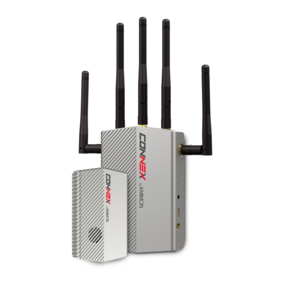
Getting Started: Air and Ground Units About CONNEX and CONNEX Mini AMIMON’s CONNEX and CONNEX mini provide a high-end, high-performance wireless HD connection that can operate in challenging unmanned air or ground platforms under harsh conditions with zero latency, such as UAV/ UGV. - Page 8 CONNEX / CONNEX Mini User Guide How CONNEX Works The figure above contains the following main components and people: Air Unit: The Air Unit is connected to a drone in order to capture video from the drone's camera and to transmit it to up to four Ground Units simultaneously (multicast), thus creating a wireless video link.
- Page 9 In the Box The CONNEX systems are comprised of an Air Unit (transmitter) and a Ground Unit (receiver). For details about the components of the Air and Ground Units and the accessories provided with each, refer to the following...
-
Page 10: Connex Air Unit (Transmitter)
Android devices. CAN bus / S.BUS NOTE : AMIMON recommends using the CONNEX link for Gimbal control ONLY and NOT for full drone control. Important: The CAN bus port and USB port (for firmware upgrade) should not be connected at the same time. - Page 11 CONNEX / CONNEX Mini User Guide Power Connector Micro USB This port enables configuration and upgrade of the Air Unit software using the Port CONNEX Management Application for Windows / MAC for Android devices. mini HDMI IN For receiving video from the camera.
- Page 12 CONNEX / CONNEX Mini User Guide Air Unit Accessories The box number in which each cable is provided is indicated in the table below. Name Description Two flat lightweight 2dbi cable Tx Cable Antennas antennas. Box 2. Cable Antenna Mounting...
-
Page 13: Connex Ground Unit (Receiver)
CONNEX / CONNEX Mini User Guide For connecting the Air Unit to the Mounting Plate drone. This item consists of two parts. Box 3. Note: For information about additional accessories, go to www.amimon.com CONNEX Ground Unit (Receiver) The following figures show both sides of the Ground Unit. - Page 14 CONNEX / CONNEX Mini User Guide Ground Unit (Receiver) – 2...
- Page 15 Battery Plate Screws: Four screws for connecting a battery plate are provided on the bottom of the Ground Unit. The battery plate, which is an optional accessory, is not included, and may be purchased from AMIMON’s website or authorized resellers.
- Page 16 CONNEX / CONNEX Mini User Guide Ground Unit Cables and Antennas The box number in which each cable is provided is indicated in the table below. Name Description Standard HDMI Cable 1.2 meters. Box 7. AC Power Adapter and Four different adapters are provided Cable for indoor use only.
-
Page 17: Connex Mini Air Unit (Transmitter)
CONNEX / CONNEX Mini User Guide Rx Antennas Five 2dbi screw-on antennas. Box 4. Standard Micro USB cable for upgrading the Ground Unit software. The Micro USB connector connects to the USB port on the Air and Micro USB Cable Ground Units. - Page 18 Windows / MAC for Android devices. NOTE : AMIMON recommends using the CONNEX link for Gimbal control ONLY and NOT for full drone control. Important: The CAN bus port and USB port (for firmware upgrade) should not be connected at the same time.
- Page 19 CONNEX / CONNEX Mini User Guide Tx Cable Two ports for connecting lightweight 2dbi cable antennas. Antenna Ports LEDs For a description of the Air Unit LEDs, refer to Behavior. The Air Unit is provided pre-paired (preregistered) with the Ground Unit that comes in the box.
- Page 20 CONNEX / CONNEX Mini User Guide Air Unit Accessories Cables and accessories for the Air Unit are described in the table below. Name Description Two flat lightweight 2dbi Tx Cable Antennas cable antennas pre- and Mounting connected to a mounting Accessories accessory.
-
Page 21: Connex Mini Ground Unit (Receiver)
(OSD). By default, OSD is enabled (displayed). Pressing this button disables and re-enables OSD. The CONNEX mini system supports up to four Ground Units per Air Unit. The Ground Unit provided out-of-the-box automatically searches for and Link Button connects to the Air Unit provided in the same box. The Link button enables you to connect up to three additional Ground Units to the same Air Unit. - Page 22 CONNEX / CONNEX Mini User Guide Power Port Input rating: 8-26 VDC. Enables you to connect the Ground Unit to a tripod. Connection to a tripod Tripod Mount Hole is optional. This port can be connected to the Remote Control trainer port. This port enables you to remotely control the gimbal on the drone using the link between the Ground Unit and the Air Unit.
- Page 23 CONNEX / CONNEX Mini User Guide Ground Unit Cables and Antennas Cables and accessories for the Ground Unit are described in the table below. Name Description Standard HDMI Cable 1.2 meters. DC plug to XT-60 Male Power Connector – 50cm length S.BUS Trainer Port...
-
Page 24: Getting Started - Air And Ground Units
Before you begin, verify that the Air Unit and Ground Unit you are working with are designed for the same product. A CONNEX Air Unit will not link with a CONNEX mini Ground Unit, and vice versa. The Air and Ground Units provided in the same box are preconfigured to automatically search for and connect to each other. -
Page 25: Chapter 3: Safety Instructions And Maintenance
Do not use the product if there is any physical damage to the enclosure. For CONNEX only - It is normal for the product to become slightly hot during use. However, if the enclosure’s temperature becomes too hot to touch, turn the product off and contact support. The internal fan of the Air... -
Page 26: Potential Hazards
Be aware and comply with all signs and instructions. It is not advisable to operate the CONNEX or CONNEX mini units while at a refueling point or service station: Users are reminded to observe restrictions on the use of radio equipment in fuel depots (fuel storage and distribution areas), chemical plants or where blasting operations are in progress. -
Page 27: Chapter 4: Specifications And Supported Features
CONNEX / CONNEX Mini User Guide Specifications and Supported Features This chapter presents: Technical Specifications Supported Remote Controls, Gimbals and Telemetry Flight Controllers Supported Resolutions... -
Page 28: Technical Specifications
CONNEX / CONNEX Mini User Guide Technical Specifications The following table presents the technical specifications for CONNEX and CONNEX mini. CONNEX CONNEX mini Transmission Up to 1,000m/3,000 ft. (LoS) Up to 500m/1,500 ft. (LoS) Distance Outdoor Transmission Delay Zero [Less than 1 msec.] Radio Frequency 5.1-5.8 GHz, according to regional regulations... -
Page 29: Supported Remote Controls, Gimbals And Telemetry Flight Controllers
CONNEX / CONNEX Mini User Guide Supported Remote Controls, Gimbals and Telemetry Flight Controllers This section lists the Air Unit camera gimbals and remote controls that are supported by CONNEX and CONNEX mini. Supported Air Unit Camera Gimbals (partial list, for pre-tested models) -
Page 30: Supported Resolutions
CONNEX / CONNEX Mini User Guide Supported Resolutions The following table lists the video formats and resolutions supported by CONNEX and CONNEX mini. Video Format Timings Format Name CONNEX CONNEX mini 40MHz 20MHz 40MHz 20MHz 720(1440) x 480i @ 59.94/60Hz 480i 640 x 480p @ 59.94/60Hz... -
Page 31: Chapter 5: Setting Up Connex
CONNEX / CONNEX Mini User Guide Setting Up CONNEX This chapter presents: Setting Up the CONNEX Ground Unit Setting up the CONNEX Air Unit Mounting the Air Unit Antenna Accessories Connecting the Telemetry/MAVLink Port Controlling the Drone Camera Gimbal Recommendations and Best Practices This chapter presents: Placement Guidelines –... - Page 32 CONNEX / CONNEX Mini User Guide Avoid Obstacles between the Antennas and the Ground Unit: Place the Air Unit cable antennas as low as possible in the drone in order to avoid line of sight obstacles between the antennas and the Ground Unit while the drone is flying.
- Page 33 CONNEX / CONNEX Mini User Guide Avoid Proximity to Metal Objects: The antennas must be at least 7 cm away from any metal object, such as the landing gear or a battery. For example, do not tie the antenna directly onto the landing gear, even if it is made of carbon.
-
Page 34: Placement Guidelines - Ground Unit
5 GHz band. Setting Up the CONNEX Ground Unit We highly recommend that you use the provided AMIMON accessories and cables. If alternate products are used, make sure that they are of the highest quality. - Page 35 CONNEX / CONNEX Mini User Guide Connecting the Ground Unit Antennas – Box 4 3. Enable display of the received video by connecting the provided Standard HDMI cable (Box 7) from the Ground Unit HDMI port to the monitor’s HDMI port (click here for details).
- Page 36 CONNEX / CONNEX Mini User Guide Ground Unit – Network LED A link has been established to the Air Unit, meaning that the Ground Unit is receiving video transmission from the Air Unit. The Network LED displays one of three colors to indicate the strength of the signal...
-
Page 37: Setting Up The Connex Air Unit
Setting Up the CONNEX Air Unit Set up the CONNEX Air Unit (transmitter) and connect it to the drone, as described in this section. We highly recommend that you use the provided AMIMON accessories and cables. If alternate products are used, make sure that they are of the highest quality. - Page 38 CONNEX / CONNEX Mini User Guide 2. Attach the mounting plate (with the Air Unit attached to it as described above) to the drone using screws or plastic ties. Typically, it can be placed on the bottom of the drone. Make sure that the Air Unit’s ventilation openings are not obstructed.
- Page 39 CONNEX / CONNEX Mini User Guide 8. The Air Unit automatically connects with the powered on Ground Units that are paired with this Air Unit. A connection is established between the Air and Ground Units regardless of whether video is transmitted on the wireless link, as follows: o If video is transmitting, the Ground Units display the video.
-
Page 40: Mounting The Air Unit Antenna Accessories
CONNEX / CONNEX Mini User Guide The Air Unit is searching for an available frequency on which to transmit. Blinks Very Slowly Note: This may take up to 70 seconds when working outdoors in Japan. Mounting the Air Unit Antenna Accessories The Air Unit antenna mounting accessories provide a variety of options for attaching the two provided flat cable antennas to the drone so that they are pointing the towards the ground (vertical). - Page 41 CONNEX / CONNEX Mini User Guide Description Drone leg/bar is here Back of the Antenna Mount Piece Description Plastic ties can be threaded through here to 1 + 2 attach this to the drone The Antenna Clamp attaches to the rotary on the Antenna Mounting Piece (shown above) using the provided screw.
-
Page 42: Connecting The Telemetry/Mavlink Port
Controlling the Drone Camera Gimbal The CONNEX Gimbal Control feature enables an operator on the ground to control the drone’s camera gimbal using various remote controls over the video uplink channel. Only gimbals that can input S.BUS are supported. -
Page 43: Chapter 6: Setting Up Connex Mini
Setting Up the CONNEX Mini Ground Unit This section describes how to set up the CONNEX mini Ground Unit (receiver). We highly recommend that you use the provided AMIMON accessories and cables. If alternate products are used, make sure that they are of the highest quality. - Page 44 CONNEX / CONNEX Mini User Guide 3. Enable display of the received video by connecting the provided Standard HDMI cable from the Ground Unit HDMI port to the monitor’s HDMI port. Standard HDMI Cable 4. Connect the provided power cable to the power port on the Ground Unit labeled 8-26-VDC, and connect the other end to a power source.
-
Page 45: Setting Up The Connex Mini Air Unit
Setting Up the CONNEX Mini Air Unit This section describes how to set up the CONNEX mini Air Unit (transmitter) and connect it to the drone. We highly recommend that you use the provided AMIMON accessories and cables. If alternate products are used, make sure that they are of the highest quality. - Page 46 CONNEX / CONNEX Mini User Guide 3. Connect the two Air Unit flat cable antennas to the two Air Unit cable antenna ports, as shown below: Connecting the Antennas to the Air Unit Ensure that the antennas are tightly fastened.
- Page 47 CONNEX / CONNEX Mini User Guide 5. Connect the provided Air Unit Power cable to the power port on the Air Unit. Air Unit Power Cable The right side of this cable goes into the Air Unit power port. The left side of this cable goes to the battery.
- Page 48 CONNEX / CONNEX Mini User Guide LED Behavior The CONNEX mini features two LED indicators: a Video LED and a Network LED. In normal operating conditions, both LEDs show a constant white color. No power (or low power) is indicated by the LEDs turning off.
-
Page 49: Connecting The Ctrl Port For Mavlink Telemetry
(such as flight mode, number of connected GPS satellites, speed, height, orientation and more). CONNEX mini supports both MAVLink telemetry and CAN bus telemetry. Verify that you are using the cable that is relevant for the telemetry option you are using. -
Page 50: Connecting The Ctrl Port For Can Bus Telemetry
(such as flight mode, number of connected GPS satellites, speed, height, orientation and more). CONNEX mini supports both MAVLink telemetry and CAN bus telemetry. Verify that you are using the cable that is relevant for the telemetry option you are using. -
Page 51: Controlling The Drone Camera Gimbal
CONNEX / CONNEX Mini User Guide Controlling the Drone Camera Gimbal The CONNEX Gimbal Control feature enables an operator on the ground to control the drone’s camera gimbal using various remote controls over the video uplink channel. Only gimbals that can input S.BUS are supported. -
Page 52: Chapter 7: Connex Operational Instructions
Multicasting to Multiple Ground Units Ground Unit – On Screen Display (OSD) The Ground Unit monitor displays information collected by the CONNEX system overlaid on the video received from the Air Unit. The following types of information can be overlaid on the video:... - Page 53 When a fixed frequency is selected, the frequency is displayed in MHz. The currently selected bandwidth. CONNEX mini systems support 40 MHz bandwidth only. Air Unit power voltage level. This arrow, which appears when three or more GPS satellites are detected, points in the direction of home.
- Page 54 CONNEX / CONNEX Mini User Guide The following information is provided: Drone height. Rotation of the drone around the axis (in degrees), relative to the North. Ground speed. Flight Mode. The following standard Arducopter flight modes may be displayed: STBL (Stabilize)
- Page 55 CONNEX / CONNEX Mini User Guide To display OSD information: While all LEDs on the Ground Unit are lit, press the OSD button on the Ground Unit. The following is an example of the OSD View: OSD View – with Telemetry Information...
-
Page 56: Alert And System Messages
CONNEX / CONNEX Mini User Guide Alert and System Messages The tables below describe messages that may appear on the monitor connected to the Ground Unit HDMI port. Alert Messages – Overlaid on Video During Link These alert messages may be displayed on top of the live video:... -
Page 57: Multicasting To Multiple Ground Units
CONNEX / CONNEX Mini User Guide Multicasting to Multiple Ground Units A single Air Unit can transmit video downlink to up to four Ground Units. This is called multicasting . The following procedure describes how to pair an additional Ground Unit with the same Air Unit. -
Page 58: Chapter 8: Connex Management Application For Windows / Mac
2. Connect the Air Unit or Ground Unit to a computer, as described in Connecting the Air Unit or Ground Unit to a Computer. Note: Only a single CONNEX Air Unit or CONNEX Ground Unit can be connected to the CONNEX Management application at a time. -
Page 59: Installing The Connex Management Application
2. Run the installation file and follow the displayed instructions to install the CONNEX Management application. 3. Launch the application by double-clicking its desktop icon. The following window displays (Air Unit on left, Ground Unit on right): The current version of the CONNEX Management application is displayed in the upper left corner of the window. -
Page 60: Message Alert When Running The Management Tool Installation Process In Win8/10
Message Alert when running the Management Tool Installation Process in Win8/10 When installing the CONNEX Management Tool in Windows 8 and Windows 10, the following alert may appear: Continue with the installation by clicking the More info link. Select the checkbox stating 'I understand the risk and want to run this app' and then click Run anyway . -
Page 61: Connecting The Air Unit Or Ground Unit To A Computer
Connecting the Air Unit or Ground Unit to a Computer The Air Unit or Ground Unit must be connected to a computer on which the CONNEX Management application is installed in order to configure or upgrade that unit. To connect the Air Unit or Ground Unit to a computer: Connect the Micro USB cable (Box 6) to the Air Unit’s or Ground Unit’s USB port. -
Page 62: Upgrading The Air Unit Or Ground Unit Firmware
CONNEX / CONNEX Mini User Guide Upgrading the Air Unit or Ground Unit Firmware If the Connex Management tool displays an alert about a newer tool version, download the new version from: http://connex.amimon.com/firmware-update Upgrading the Air Unit or Ground Unit firmware does not affect the settings of the wireless video downlink. - Page 63 CONNEX / CONNEX Mini User Guide 3. Click the Upgrade button. The latest software version is automatically downloaded from the AMIMON server and installed on the connected unit. The lower portion of the window displays the progress of the upgrade and lists the processes as they are performed, as shown below: 4.
-
Page 64: Configuring The Link Between The Ground And Air Units
This article describes how to configure the link between an Air Unit and its Ground Units. This procedure is performed on an Air Unit only. The Link Configuration tab of the Management application is shown in the following figures (CONNEX on left, CONNEX mini on right). The link parameters are described in the table below the diagrams. - Page 65 CONNEX / CONNEX Mini User Guide To configure the link: 1. Make sure that the computer on which the CONNEX Management application is installed is connected to the Air Unit via a Micro USB cable and is connected to the Internet.
-
Page 66: Checking The Ground Units Registered To An Air Unit
This article explains how to check which Ground Units are paired with a specific Air Unit. To verify which Ground Units are registered to an Air Unit: 1. Make sure that the computer on which the CONNEX Management application is installed is connected to the Air Unit via a Micro USB cable. -
Page 67: Unregistering Ground Units
To unregister a single device: 1. Make sure that the computer on which the CONNEX Management application is installed is connected to the Internet and is connected to the Air Unit via a Micro USB cable. 2. Launch the CONNEX Management tool by double-clicking its desktop icon. - Page 68 CONNEX / CONNEX Mini User Guide To unregister all Ground Units: 1. Make sure that the computer on which the CONNEX Management application is installed is connected to the Internet and is connected to the Air Unit via a Micro USB cable.
-
Page 69: Configuring Fail Safe Parameters
Hold: The most recent value (prior to the communication loss) is maintained. Set: A new value is used. Values are configured in % (from -100 to +100). IMPORTANT: It is recommended to utilize the CONNEX link for Gimbal control ONLY and NOT for full drone control. - Page 70 CONNEX / CONNEX Mini User Guide To set Fail Safe parameters: 1. Make sure that the computer on which the CONNEX Management application is installed is connected to the Air Unit via a Micro USB cable and is connected to the Internet.
-
Page 71: Chapter 9: Connex Management Application For Android Devices
2. Connect the Air Unit or Ground Unit to a mobile device, as described in Connecting the Air Unit or Ground Unit to a Mobile Device. Note: Only a single CONNEX Air Unit or CONNEX Ground Unit can be connected to the CONNEX Management application at a time. -
Page 72: Installing The Connex Management Application
CONNEX / CONNEX Mini User Guide Installing the CONNEX Management Application The CONNEX Management application for mobile devices is currently supported on Android devices with operating systems 4.4 and higher. In addition, the mobile device needs to support USB OTG capability. -
Page 73: Connecting The Air Or Ground Unit To Your Mobile Device
Connecting the Air or Ground Unit to Your Mobile Device The Air Unit or Ground Unit must be connected to a mobile device on which the CONNEX Management application is installed in order to configure that unit. To connect the Air Unit or Ground Unit to a mobile device: Connect the USB to Micro USB connector to the Air Unit’s or Ground Unit’s USB port. -
Page 74: Working With The Connex Mobile Application
Firmware Version: The version of the firmware currently installed on the unit. The application automatically checks with the AMIMON server whether the latest firmware version of the connected unit is installed. If the latest version is installed, a Firmware Version is Up to Date message is displayed. - Page 75 Ground Units that are registered with the Paired Devices connected Air Unit, and enables you to unregister or more of them. Control Configuration Allows you to view and modify Fail Safe parameters. Support Redirects you to the CONNEX online Help Center.
- Page 76 CONNEX / CONNEX Mini User Guide Basic Application Components This section explains general features that enable you to work with the mobile application quickly and effectively. The components are described in the table below the diagram. Number Feature Name Description Navigation button Use this button to navigate back to the main menu.
-
Page 77: Configuring The Link Between The Ground And Air Units
This article describes how to configure the link between an Air Unit and its Ground Units. This procedure is performed on an Air Unit only. The Link Configuration screen of the Management application is shown in the following figures (CONNEX on left, CONNEX mini on right). The link parameters are described in the table below the diagrams. - Page 78 To configure the link: 1. Make sure that the mobile device on which the CONNEX Management application is installed is connected to the Air Unit via a USB to Micro USB cable and is connected to the Internet. 2. Launch the CONNEX Management application, and navigate to the Link Configuration screen.
-
Page 79: Checking The Ground Units Registered To An Air Unit
This article explains how to check which Ground Units are paired with a specific Air Unit. To verify which Ground Units are registered to an Air Unit: 1. Make sure that the mobile device on which the CONNEX Management application is installed is connected to the Air Unit via a USB to Micro USB cable. -
Page 80: Unregistering Ground Units
Unregistering all devices simultaneously To unregister a single device: 1. Make sure that the mobile device on which the CONNEX Management application is installed is connected to the Internet and is connected to the Air Unit via a USB to Micro USB cable. - Page 81 CONNEX / CONNEX Mini User Guide To unregister all Ground Units: 1. Make sure that the mobile device on which the CONNEX Management application is installed is connected to the Internet and is connected to the Air Unit via a USB to Micro USB cable.
-
Page 82: Configuring Fail Safe Parameters Ii
Hold: The most recent value (prior to the communication loss) is maintained. Set: A new value is used. Values are configured in % (from -100 to +100). IMPORTANT: It is recommended to utilize the CONNEX link for Gimbal control ONLY and NOT for full drone control. - Page 83 CONNEX / CONNEX Mini User Guide To set Fail Safe parameters: 1. Make sure that the mobile device on which the CONNEX Management application is installed is connected to the Air Unit via a USB to Micro USB cable and is connected to the Internet.
Need help?
Do you have a question about the CONNEX and is the answer not in the manual?
Questions and answers