
Related Manuals for AMIMON CONNEX

Summary of Contents for AMIMON CONNEX
- Page 1 CONNEX User Guide CONNEX User Guide Simply Plug-and-Fly! Version 1.0 www.amimon.com...
-
Page 2: About This Guide
Chapter 4, CONNEX Management Application, page 37, describes how to configure and • upgrade the CONNEX Air Unit and Ground Unit. For a quick summary of the essential steps for setting up quickly, you may refer to the CONNEX Quick Start Guide. Support and Contacting Information Support: www.AMIMON.com/support... - Page 3 Resale of AMIMON products or services with statements different from or beyond the parameters stated by AMIMON for that product or service voids all express and any implied warranties for the associated AMIMON product or service and is an unfair and deceptive business practice.
-
Page 4: Safety Instructions And Maintenance
Accessories (including cables) must not be replaced, as they may affect performance or functionality or damage the unit. We highly recommend that you use the provided Amimon cables. If an alternate cable is used, make sure that it is of the highest quality. - Page 5 Be aware and comply with all signs and instructions. It is not advisable to operate the CONNEX units while at a refueling point or service • station: Users are reminded to observe restrictions on the use of radio equipment in fuel depots (fuel storage and distribution areas), chemical plants or where blasting operations are in progress.
-
Page 6: Table Of Contents
Ground Unit (Receiver) ......................15 Chapter 2, Setting Up CONNEX ............ 19 Setting Up the CONNEX Air Unit ..................19 Connecting the Telemetry Port ....................23 Placement Guidelines – Air Unit Cable Antennas ..............23 Air Unit Antenna Mounting Accessories ................25 Setting Up the CONNEX Ground Unit ................ - Page 7 Supported Gimbal Remote Controls ................48 Supported Flight Controllers for Telemetry ..............48 Appendix C, Supported Resolutions ..........49 Appendix D, Limitation of Liability and Warranty ......50 Appendix E, FCC Caution ..............51 FCC Radiation Exposure Statement ................. 51 About Amimon ........................52...
- Page 8 CONNEX User Guide Blank Page for Double-sided Printing...
-
Page 9: Chapter 1, Introducing Connex
Amimon’s CONNEX provides a high-end, high-performance wireless HD connection that can operate in challenging unmanned air or ground platforms under harsh conditions with zero latency, such as UAV/UGV. The small and lightweight CONNEX system transmits commercial, industrial, inspection and monitoring video in real time to its Ground Unit, which can be located up to 1,000 meters away. -
Page 10: Key Features
Plug-and-Fly, ready to operate out of the box • DFS support enables multiple free channels, thus boosting robustness • In the Box CONNEX is comprised of the following components: Air Unit (Transmitter), page 11 • Ground Unit (Receiver), page 15 •... -
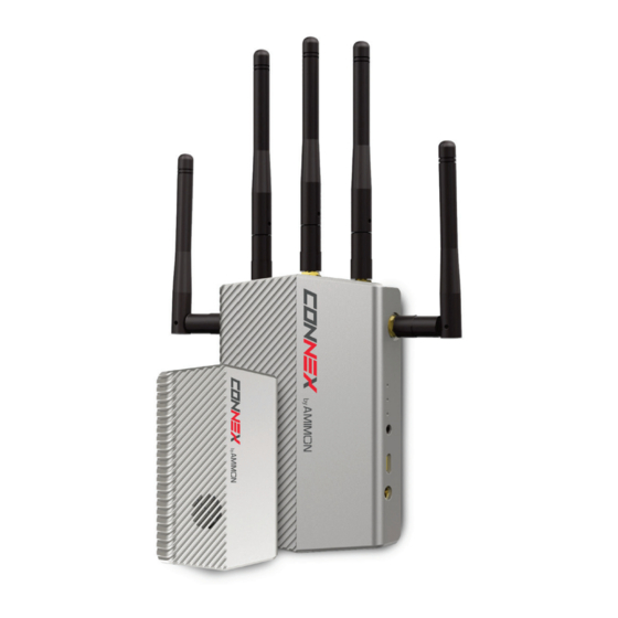
Page 11: Air Unit (Transmitter)
S.BUS protocol or directly to an Air Unit receiver for the purpose of controlling the camera gimbal. S.BUS properties can be configured using the CONNEX Management application, which runs on the computer connected to the Ground Unit, as described in Chapter 4, CONNEXTM Management Application on page 37. - Page 12 CONNEX User Guide For a description of the Air Unit LEDs, you may refer to: Table 3: Air Unit – Power LED • Table 4: Air Unit – Video LED • Table 5: Air Unit – Network LED • Air Unit Accessories The box number in which each cable is provided is indicated below.
- Page 13 CONNEX User Guide S-BUS Cable 5-pin JST to S-BUS female – 50cm length. Box 6. Figure 6: S-BUS Cable Telemetry Cable 6-pin JST female to 6-pin DF13 – 50cm length. Box 6. Figure 7: Telemetry Cable Air Unit Power Cable 4-pin JST to XT-60 Male –...
- Page 14 CONNEX User Guide Mounting Plate For connecting the Air Unit to the aircraft. This item consists of two parts. Box 3. Figure 10: Mounting Plate Note: For information about additional accessories, go to www.AMIMON.com.
-
Page 15: Ground Unit (Receiver)
Power Port: 7-17VDC voltage. Micro USB Port: This port enables configuration and upgrade of the Ground Unit software using the CONNEX Management application, as described in Chapter 4, CONNEXTM Management Application section on page 37. S.BUS Trainer: This port can be connected to the Futaba Remote Control trainer port. This port... - Page 16 OSD and pressing this button again redisplays it. Link Button: The CONNEX system supports up to four Ground Units per Air Unit. The Ground Unit is provided out-of-the-box to automatically search for and connect to the Air Unit that is provided in the same box.
- Page 17 CONNEX User Guide Ground Unit Cables and Antennas The box number in which each cable is provided is indicated below. Standard HDMI Cable 1.2 meters. Box 7. Figure 13: Standard HDMI Cable AC Power Adapter and Cable Four different adapters are provided for indoor use only. Box 5.
- Page 18 CONNEX User Guide Rx Antennas Five 2dbi screw-on antennas. Box 4. Figure 16: Rx Antennas Micro USB Cable Standard Micro USB cable for upgrading the Ground Unit software. The Micro USB connector connects to the USB port on the Ground Unit.
-
Page 19: Chapter 2, Setting Up Connex
Setting Up the CONNEX Ground Unit, page 26 • Setting Up the CONNEX Air Unit Set up the CONNEX Air Unit (transmitter) and connect it to the aircraft, as described in this section. We highly recommend that you use the provided Amimon cables. If an alternate cable is used, make sure that it is of the highest quality. - Page 20 CONNEX User Guide If attaching the Air Unit to a bar on the aircraft, then perform the following before attaching the Air Unit to the mounting plate: A clear plastic holder is provided to help attach the mounting plate to a bar or •...
- Page 21 CONNEX User Guide 4 Connect the two Air Unit flat cable antennas to the two Air Unit cable antenna ports, as shown below: Figure 20: Connecting the Antennas to the Air Unit 5 Connect the provided Micro to Mini HDMI cable (Figure 5) from the HDMI IN port on the Air Unit to the camera.
- Page 22 CONNEX User Guide Table 3: Air Unit – Power LED On (White) The Air Unit is powered on. No power is being supplied to the Air Unit. Blinks Indicates a system error. Quickly 8 The Air Unit automatically connects with the powered on Ground Units that are paired with this Air Unit.
-
Page 23: Connecting The Telemetry Port
CONNEX User Guide Connecting the Telemetry Port The following describes how to connect the Air Unit Telemetry port to the aircraft’s flight controller so that the Ground Unit monitor can display information received from the aircraft’s flight controller overlaid on the video, such as flight mode, number of connected GPS satellites, speed, height, orientation and more. - Page 24 CONNEX User Guide Avoid Proximity to Metal Objects: The antennas must be at least 7 cm away from • any metal object, such as the landing gear or a battery. For example do not tie the antenna directly onto the landing gear even if it is made of carbon. The mounting accessories enable you to attach the antennas while leaving the required distance.
-
Page 25: Air Unit Antenna Mounting Accessories
CONNEX User Guide Air Unit Antenna Mounting Accessories The Air Unit antenna mounting accessories provide a variety of options for attaching the two provided flat cable antennas to the aircraft so that they are pointing the towards the ground (vertical). -
Page 26: Setting Up The Connex Ground Unit
User Guide Setting Up the CONNEX Ground Unit We highly recommend that you use the provided Amimon cables. If an alternate cable is used, make sure that it is of the highest quality. To set up the CONNEX Ground Unit: 1 Refer to the Placement Guidelines –... -
Page 27: Placement Guidelines - Ground Unit
CONNEX User Guide Table 8: Ground Unit – Network LED A link has been established to the Air Unit, meaning that the Ground Unit is receiving video transmission from the Air Unit. The Network LED displays one of three colors to indicate the strength of the signal received... - Page 28 CONNEX User Guide Blank Page for Double-sided Printing...
-
Page 29: Chapter 3, Using Connex
To get started with the Air Unit: 1 Set up the Air Unit, as described in the Setting Up the CONNEX Air Unit section on page 19. 2 The Air Unit can be configured to transmit video downlink to up to three additional Ground Units, as described in the Multicasting to Multiple Ground Units section on page 34. -
Page 30: Ground Unit - On Screen Display (Osd)
User Guide Ground Unit – On Screen Display (OSD) The Ground Unit monitor displays information collected by the CONNEX system overlaid on the video received from the Air Unit. The following types of information can be overlaid on the video: Default, below •... -
Page 31: Additional Telemetry Information Overlaid On Video
CONNEX User Guide Additional Telemetry Information Overlaid on Video Additional telemetry information can be overlaid on the video received from the aircraft’s flight controller. This information appears in a black strip on the top of the video, as shown below:... - Page 32 CONNEX User Guide SPRT Sport : Number of Connected GPS Satellites. : Aircraft Battery Charge. This additional information is displayed when: The aircraft has a MAVLink-based flight controller. • The Air Unit Telemetry port is connected to the aircraft’s flight controller, as •...
-
Page 33: Alert And System Messages
CONNEX User Guide Alert and System Messages The following describes the messages that may appear on the monitor connected to the Ground Unit HDMI port. Alert Messages – Overlaid on Video during Link These alert messages may be displayed on top of the live video. -
Page 34: Multicasting To Multiple Ground Units
Pairing Additional Ground Units with an Air Unit To pair an additional Ground Unit with an Air Unit: 1 Set up the additional Ground Unit, as described in the Setting Up the CONNEX Air Unit section on page 26. The Ground Unit must be placed between one and 10 meters from the Air Unit. - Page 35 CONNEX User Guide 4 Press and hold the Link button on the Ground Unit. The following message is then displayed: Pairing in progress After a while, the monitor connected to the Ground Unit should display the video received from the Air Unit, as described in the Ground Unit – On Screen Display (OSD) section on page 30.
-
Page 36: Controlling The Aircraft Camera Gimbal
4 The default gimbal command transmission bit rate is FASSTest 12CH Mode (6.3m sec). If this bit rate is not supported by the gimbal controller, then use the CONNEX Management application to configure the S.BUS Bit Rate manually, as described in the Configuring the Link section on page 42. -
Page 37: Chapter 4, Connex Management Application
2 Connect the Air Unit or Ground Unit to a computer, as described in the Connecting the Air Unit or Ground Unit to a Computer section on page 39. Note: Only a single CONNEX Air Unit or CONNEX Ground Unit can be connected to the CONNEX Management application at a time. -
Page 38: Installing The Connex Management Application
1 Download the latest version from the Amimon website www.AMIMON.com/connex/management to a computer connected to a Ground Unit. 2 Run the installation file and follow the displayed instructions to install the CONNEX Management application. 3 Launch the application by double-clicking its desktop icon. The following window displays:... -
Page 39: Connecting The Air Unit Or Ground Unit To A Computer
Connecting the Air Unit or Ground Unit to a Computer The Air Unit or Ground Unit must be connected to a computer on which the CONNEX Management application is installed in order to configure or upgrade that unit. To connect the Air Unit or Ground Unit to a computer: Connect the Micro USB cable (Box 6) to the Air Unit’s or Ground Unit’s USB port... -
Page 40: Upgrading The Air Unit Or Ground Unit Firmware
To upgrade the Air Unit or Ground Unit firmware: 1 Make sure that the computer on which the CONNEX Management application is installed is connected to the Internet and is connected to the Air Unit/Ground Unit via a Micro USB cable. - Page 41 3 Click the Upgrade button. The latest software version is automatically downloaded from the Amimon website and installed on the connected unit. The bottom of the window displays the progress of the upgrade and lists the processes as they are...
-
Page 42: Configuring The Link
Region Figure 40: Link Configuration To configure the link: 1 Make sure that the computer on which the CONNEX Management application is installed is connected to the Air Unit via a Micro USB cable and is connected to the Internet. - Page 43 5 The SBUS Rate field specifies the data rate of the S.BUS link between the Ground Unit and the Air Unit that controls the Air Unit’s camera gimbal. CONNEX configures the data rate of the S.BUS remote control to be 6.3mSec (FASSTest 12CH) by default.
-
Page 44: Checking The Ground Units Registered To An Air Unit
Air Unit, as shown below: Ground Units Registered to the Air Unit Figure 41: Registered Receivers The MAC ID of a specific Ground Unit can be seen using the CONNEX Management application as described on page 40. -
Page 45: Unregistering All Ground Units
Note: There is no option to unregister one Ground Unit at a time. To unregister all Ground Units from a specific Air Unit: 1 Make sure that the computer on which the CONNEX Management application is installed is connected to the Internet and is connected to the Air Unit via a Micro USB cable. - Page 46 CONNEX User Guide Blank Page for Double-sided Printing...
-
Page 47: Appendix A, Technical Specifications
CONNEX User Guide Appendix A, Technical Specifications Table 14: CONNEX Technical Specifications Transmission Distance Up to 1,000m/3,000 ft. (LoS) Outdoor Transmission Delay Zero [Less than 1 msec.] Radio Frequency 5.1-5.8 GHz, 17 channels Channel Selection Automatic frequency selection [AFS] 60/59.94, 1080p/50, 1080i/60, 1080i/50, 30/29.97, 24/23.98, Video Formats 60/59.94, 720p/50, 480i/60, 576i/50... -
Page 48: Appendix B, Supported Remote Controls, Gimbals And Telemetry Flight Controllers
Controls, Gimbals and Telemetry Flight Controllers The following lists the Air Unit camera gimbals and the remote controls that are supported by CONNEX. Supported Air Unit Camera Gimbals DJI – Zenmuse Z15 Zenmuse Z15-GH4 (HD) –, support S.BUS 6.3ms mode only •... -
Page 49: Appendix C, Supported Resolutions
CONNEX User Guide Appendix C, Supported Resolutions This appendix lists the video resolutions supported by CONNEX. Table 12: CONNEX Supported Resolutions Video Format Timings Format Name 40MHZ Supported 20MHz Supported Primary CEA Video Formats 720(1440) x 480i @ 59.94Hz 480i 720(1440) x 480i @ 60Hz 640 x 480p @ 59.94/60Hz... -
Page 50: Appendix D, Limitation Of Liability And Warranty
CONNEX product, even if the company has been advised of the possibility of such damages. -
Page 51: Appendix E, Fcc Caution
CONNEX User Guide Appendix E, FCC Caution Any changes or modifications not expressly approved by Amimon may void the user’s authority to operate this equipment. Note: This equipment has been tested and found to comply with the limitations for a Class B digital device, pursuant to part 15 of the FCC Rules. -
Page 52: About Amimon
CONNEX User Guide About Amimon Established in 2004, AMIMON develops and manufactures HD wireless video systems recognized as the standard solution of realtime wireless video for the pro-Camera, unmanned, medical, A/V installation and other markets. Its highly disruptive digital and RF semiconductor video modem technology addresses the stringent requirements of realtime HD video connectivity augmented by multicast and control capabilities.
Need help?
Do you have a question about the CONNEX and is the answer not in the manual?
Questions and answers