Table of Contents
Advertisement
Quick Links
Advertisement
Table of Contents

Related Manuals for ATS BBR2S


Summary of Contents for ATS BBR2S
- Page 1 INSTRUCTION MANUAL BBR2S Bending Beam Rheometer This manual contains important operating and safety information. Carefully read and understand the contents of this manual prior to the operation of this equipment. www.atspa.com MAN - BBR2S - REV: Original...
- Page 2 Information in this document is subject to change without notice and does not represent a commitment on the part of Applied Test Systems (ATS). © Copyright Applied Test Systems 2018 For assistance with set-up or operation, contact the ATS service department. Please have this manual and product serial number available when you call. Telephone: +1-724-283-1212.
-
Page 3: Table Of Contents
Linear Variable Differential Transformer (LVDT) ..................9 Load Cell ...............................10 Resistance Temperature Detector (RTD) ....................10 Computer Control System Software .....................10 Mechanical Refrigeration Unit .......................10 Accessories ............................10 Controls ..............................11 D. Installation ........................... 12 D.1 Recommended Tools ...........................12 MAN - BBR2S - REV: Original... - Page 4 D.4 Connecting Equipment ..........................15 D.5 BBR2S Software Installation ........................17 E. Operation .............................20 E.1 Filling the Bath .............................20 E.2 Power Up the BBR2S ..........................20 E.3 Overview of Touchscreen and Menus ......................20 E.4 Editing Users and Permissions ..........................22 Operator Name Field ..........................23 Password Field ............................23...
- Page 5 F.1 Preface .................................38 F.2 Load Shaft Stuck or Stalled During Verification or Standardization ............38 G. Maintenance ..........................40 G.1 General Maintenance ..........................40 Appendix A: Warranty ........................41 Appendix B: Wiring Diagrams .......................42 Appendix C: Image Glossary ......................44 MAN - BBR2S - REV: Original...
-
Page 6: Introduction
Retain all cartons and packing materials until the unit is operated and found to be in good condition. If damage has occurred during shipping, notify Applied Test Systems (ATS) and the carrier immediately. If it is necessary to file a damage claim, retain the packing materials for inspection by the carrier. -
Page 7: Safety
B. Safety B.1 For Owners, Operators, and Maintenance All ATS equipment is designed to be operated with the highest level of safety. This manual uses note, caution, and warning symbols throughout to draw your attention to important operational and safety information. -
Page 8: Cautions
BBR. CAUTION: Carefully place the calibration weights on the load cell’s weight plan. If the Linear Variable Differential Transducer (LVDT) shaft is bumped, it may become inaccurate or even permanently damaged. MAN - BBR2S - REV: Original | B. Safety... -
Page 9: System Overview
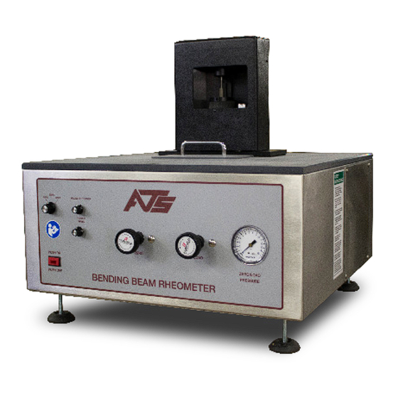
Front of Unit 1. Load Frame 5. Zero/Load Pressure Gauge 2. Power Switch 6. Zero Regulator 3. Mode Select Switch 7. Load Regulator 4. Stirrer Motor Controls Figure C.1: BBR2S Front MAN - BBR2S - REV: Original | C. System Overview... -
Page 10: Back Of Unit
4. Chiller RTD (Connects to Back of Chiller) 2. Air Connections to Load Frame 5. USB Connection to BBR Computer 3. AC Power Connection 6. Load Frame Sensor Cables Figure C.2: BBR2S (Rear View) MAN - BBR2S - REV: Original | C. System Overview... -
Page 11: Gauge Kit
Figure C.3: BBR2S Gauge Kit 1. Step Disk 5. Confidence Beam 2. 50 gram cal. weights (4) 6. Load Shaft 3. 2 gram weights (2) 7. Anvil Support Adapters (2) 4. Non-Compliant Beam MAN - BBR2S - REV: Original | C. System Overview... -
Page 12: General Product Description
Strategic Highway Research Program (SHRP) Test, Method B-002, AASHTO Designation T313, and ASTM D 6648. The BBR2S’s design does not allow it to perform any additional functions other than the intended functions specified in this manual. -
Page 13: Recommended Tools
Protective eye wear and gloves for use during testing. Environmental Conditions The BBR2S is designed for use in an industry/laboratory setting in an indoor and dry environment. The Base Unit should be placed on a clean, stable work surface with the connecting mechanical refrigeration unit nearby. The mechanical refrigeration unit should be placed 6 in. -
Page 14: Specimen Support
CAUTION: The load cell can be easily damaged, especially from side loading and excessive torque. Use caution while handling the test frame when the loading shaft is attached. Remove loading shaft before laying load frame on its side, especially before shipping. MAN - BBR2S - REV: Original | C. System Overview... -
Page 15: Load Cell
Computer Control System Software The computer control system software provides user control of the BBR2S system in a Windows® environment with keyboard and/or mouse access to these functions. The software provides pull-down menus, button selections, and data entry text boxes for easy updates and access to information. -
Page 16: Controls
Load Calibration Weights: Four 50 gram and two 2 gram load cell calibration weights are supplied with the BBR2S. These weights are placed on the load frame weight pan during load cell verification. The weights are also used to calibrate the load cell and ensure system compliance. -
Page 17: Installation
1. Remove the base unit and the refrigeration unit from the box, and place them on a sturdy work surface. WARNING: Position the BBR2S in a well-ventilated area. Consider that flammable vapors may be emitted from the bath during operation. Refer to fluid manufacturer’s MSDS documentation for further information. -
Page 18: Assembling The Load Nose
Figure D.2 - Foam Inside Load Shroud of the Load Shroud 3. Retrieve the load nose from the BBR2S gauge kit. Place the load nose in the upper portion of the load shroud. MAN - BBR2S - REV: Original | D. Installation... - Page 19 6. To re-attach the lower portion of the load shroud, place the lower portion of the shroud on a flat surface. CAREFULLY lift the load frame, and position it so that the load nose is directly above the lower portion of the MAN - BBR2S - REV: Original | D. Installation...
-
Page 20: Connecting Equipment
Load Shroud Shroud portion of Load Shroud D.4 Connecting Equipment The following hoses and cables are shipped with the BBR2S. Use them for connecting the BBR2S equipment and refer to Figure D.10 on p.16. • Zero/Load Hose (Item 2) •... - Page 21 2. Air Connections to Load Frame (Air Hose & 5. USB Connection to BBR Zero/Load Hose) Computer 3. AC Power Connection 6. Load Frame Sensor Cables Figure D.10 - BBR2S Connections MAN - BBR2S - REV: Original | D. Installation...
-
Page 22: Bbr2S Software Installation
If the BBR2S has been purchased with a computer supplied by Applied Test Systems, the necessary hardware drivers and the BBR operating software will have already been installed and set-up at ATS. If you have purchased a computer supplied by ATS, the following steps are not required to complete the installation of your BBR2S. - Page 23 4. Entering the BBR Serial Number in the BBR2S Config. File • The Serial Number information for the BBR is stored in the BBR2S.cfg file. , which is located inside of the config. directory in the BBR2S program file directory in the ATS folder on the computer’s C: drive. Figure D.11 shows the pathway to this file.
- Page 24 • In the BBR2S.cfg file, locate the line which says “Serial Number = 12-34567-8.” Edit this line such that the 12-34567-8 is replaced with either the Serial Number of the BBR as shown on the nameplate on the back of the load frame, or with whatever designation you prefer.
-
Page 25: Operation
Refer to individual test specifications for fluid type. E.2 Power Up the BBR2S 1. Press the power button on the rear of the BBR2S base unit. The power indicator light on the front of the unit will illuminate. 2. Turn on the refrigeration unit (chiller) by flipping the power switch in the rear of the unit. - Page 26 Figure E.1 - BBR2S Software Screen map MAN - BBR2S - REV: Original | E. Operation...
-
Page 27: Editing Users And Permissions
The lower part on the screen shows values for machine temperature, load, and deflection. It also has system status lights and controls for the machine. NOTE: The “Exit” button on the bottom right of the screen will exit the BBR2S program and return to Windows. To return to the Main Menu screen from any other BBR2S software screen, press the “Main Menu”... -
Page 28: Operator Name Field
Makes a copy of a selected user under a new name. This is useful if you need to make a new user with similar permissions as a current user. Press “Save” when complete. MAN - BBR2S - REV: Original | E. Operation... -
Page 29: New Button
NOTE: The standardization button will not be shown on the main menu unless the currently logged in user has permission to perform standardization. The BBR2S’s system status lights, located at the bottom right of the screen, indicate whether or not a component requires standardization. - Page 30 EXACTLY AS DESCRIBED. Failure to perform all steps of the standardization procedure may result in incorrect or erratic operation of the BBR2S. 1. Standardizing the Temperature (RTD) NOTE: Before beginning temperature standardization, verify that the temperature of the BBR bath has been set to 0.0 degrees C and allowed to stabilize for at least 1-2 hours . All temperature settings for the BBR bath are performed using the up/down arrows on the front panel of the chiller’s temperature controller.
- Page 31 Press the “Deflection” button on the Standardization Screen. b. With the load frame in the bath, remove any beams from the supports and any weights from the BBR2S. c. Adjust the zero regulator to raise the load nose to its highest position.
-
Page 32: Verification Process
E.6 Verification Process Verification of most BBR2S components will need to occur every 24 hours - this is usually done at the beginning of a day of testing. You will need a BBR2S gauge kit and a calibrated thermometer (see RTD) to perform a verification. - Page 33 2. Verify the information entered in the Confidence Beam Serial # section matches the information on the certification of conformance form that was shipped with the BBR2S. Make corrections if necessary. 3. Press the verification button to begin the verification sequence.
- Page 34 Place Confidence Beam on the sample supports. c. Apply two 50g weights to the weight pan. d. Press “Record”. e. Apply two additional 50g weights to the weight pan and press “Record”. MAN - BBR2S - REV: Original | E. Operation...
- Page 35 If the difference between the two measurements is 1.0mm or less, press the “Verification” button followed by the “Finish” button. i. If the difference between the two measurements is more than 1.0mm, press “Standardization Required” and MAN - BBR2S - REV: Original | E. Operation...
-
Page 36: Test Setup
Applied Test Systems Service Department at +1-724-283-1212. E.7 Test Setup Test setup is used to define a BBR2S test specification as well as the type of report it will generate. When you press the SETUP button the screen shown in Figure E.7 will display. -
Page 37: Creating A New Test
The data report is most often used to chart in Excel or another similar program to generate additional calculations or graphs. Figure E.9 - Standard Report Figure E.10 - Data Report MAN - BBR2S - REV: Original | E. Operation... -
Page 38: Deflection Plot And Load Plot
Test setup will need to be done before you run a test. See Section E.7 for more details if you have not already set up your test. When you press the TEST button the run screen shown in Figure E.11 will display. Figure E.11 - Run Test main screen MAN - BBR2S - REV: Original | E. Operation... -
Page 39: Load Setup
Load Setup 1. Load the non-compliant beam on the specimen supports. 2. The load control switch is located on the front of the BBR2S. Make sure the switch has been set to ZERO before proceeding. (Figure E.12). Figure E.12 - Load Control Switch 3. -
Page 40: Start Test
6. When the test is complete the system will automatically generate a report and display it. 7. If you have connected a printer to your BBR2S, you can print the test summary report from this screen. To do so, select file and then print. -
Page 41: View Test
You should not have permission for this screen unless you are experienced with the machine and what it does. There are no safety features in this screen. It should mostly be use for maintenance to trouble shoot I/O problems. MAN - BBR2S - REV: Original | E. Operation... -
Page 42: Analog Inputs Ai1, Ai2, And Ai3
High speed pulse outputs. Use a scope to test the output pin and verify that it matches the frequency and duty cycle entered in the diagnostics screen. DO3 and DO4 are not used at this time. MAN - BBR2S - REV: Original | E. Operation... -
Page 43: Troubleshooting
Listed within this section are the most common troubleshooting errors that operators may encounter when using the BBR2S. Users may follow the steps provided to work through these basic errors. Any additional issues or system errors should be brought to the attention of the Applied Test Systems Service Department immediately by calling +1-724-283-1212 or emailing service@atspa.com. - Page 44 Figure F.1 - LVDT Shaft 2. If the LVDT shaft appears to be centered in the LVDT, re-secure the cover and contact ATS for assistance. 3. If you determine that the shaft is misaligned, attempt to center it by performing the steps below.
-
Page 45: Maintenance
G.1 General Maintenance When cleaning the surface of the BBR2S, first disconnect all power sources and place all controls in an OFF position. Use a very mild cleaning agent and be careful not to allow the cleaning agent to enter and contaminate the fluid bath. -
Page 46: Appendix A: Warranty
The aforementioned provisions do not extend the original warranty period of any article that has been either repaired or replaced by Applied Test Systems. Applied Test Systems reserves the right to change published specifications. MAN - BBR2S - REV: Original | Appendix A: Warranty... -
Page 47: Appendix B: Wiring Diagrams
Appendix B: Wiring Diagrams MAN - BBR2S - REV: Original | Appendix B: Wiring Diagrams... - Page 48 MAN - BBR2S - REV: Original | Appendix B: Wiring Diagrams...
-
Page 49: Appendix C: Image Glossary
Figure E.12 - Load Control Switch..........................34 Figure E.13 - View Test main software screen ......................36 Figure E.14 - Diagnostics main software screen ....................... 37 Figure F.1 - LVDT Shaft ............................. 39 MAN - BBR2S - REV: Original | Appendix C: Image Glossary...
Need help?
Do you have a question about the BBR2S and is the answer not in the manual?
Questions and answers