
Related Manuals for Diatest DIATRON 2200

Summary of Contents for Diatest DIATRON 2200
- Page 1 DIATRON 2200 Instruction Manual DIATRON2200 Column Gauge Document No. : DT2200/EN/V2 Edition: 03/2011 © Copyright : DIATEST Hermann Költgen GmbH...
-
Page 2: Table Of Contents
Manual DIATRON 2200 Contents 1. Introduction 1.1 General information......................... 4 1.2 Measuring and display features ...................... 4 1.3 Front and rear panel ........................5 1.4 Dimensions ............................. 6 1.5 Hole pattern for interconnection ..................... 6 1.6 Technical data ..........................7 2. - Page 3 Manual DIATRON 2200 5.4 Requesting measured values ......................36 5.5 Transfer of measured data ....................... 36 5.6 Importing measurement values into Windows applications ............36 5.7 Importing measurement values into MS-EXCEL ................36 6. Male connector pin assignments 6.1 Measuring controller connectors ...................... 37 6.2 Termina blocks for accessories ......................
-
Page 4: Introduction
Manual DIATRON 2200 Introduction 1.1 General information The DIATRON2200 column gauge is an electronic gauge for connecting 1 to 4 inductive probes (on request also other modules are available). The column gauge allows the manual or automatic selec- tion of 1 to 4 gauges, including static and dynamic meas- uring programmes and the optional selection (grading) of workpieces in up to 30 classes. -
Page 5: Front And Rear Panel
Manual DIATRON 2200 Column display ranges ± 5.0000 mm ± 0.50000 ″ The 3-colour column display ( red, green, yellow ) ± 1.5000 mm ± 0.15000 ″ features an automatic colour selection according ± 0.5000 mm ± 0.05000 ″ to the tolerance limits. -
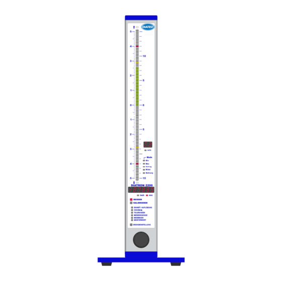
Page 6: Dimensions
Manual DIATRON 2200 Dimensions Picture: Column display with base Picture: Column display with base... -
Page 7: Technical Data
Manual DIATRON 2200 1.6 Technical data Mechanical characteristics Case Aluminium anodised, plastic top and bottom parts Base plate Aluminium powder-coated Front panel Plexiglass Control element Rotary encoder with button (16 detents / rotation) 56 x 418.5 x 86 mm / 1340g ( incl. Base plate Dimensions W x H x D / Weight ( DIATRON2200 incl. -
Page 8: Getting Started
Manual DIATRON 2200 Getting started 2.1 Delivered items Column gauge, base with 4 screws ( M3x8 ) for fixing, instruction manual, programming card, and a 2.0 mm Allen key. Further accessories, such as measuring controllers, power supply modules, measurement modules, foot switches, or adaptors according to shipping order. -
Page 9: Connecting The Modules
Manual DIATRON 2200 A DIATRON2200 column gauge that comprises modules is configured in a fixed order. If one single DIATRON2200 is to be configured, the power supply model ( 1 ) always has to be fitted first, followed by the measuring controller module ( 2 ) and then finally ( starting with no. 3 ) the measuring and interface modules in no fixed order. -
Page 10: Fitting Modules In Diatron2200 Column Gauges
Manual DIATRON 2200 2.3.3 Fitting modules into the DIATRON2200 column gauge Once the modules have been connected, they are slid into the DIATRON2200 column section as a package from the top and are then screwed to the column base using both cross-recessed screws. -
Page 11: Fitting Of Diatron2200 Column Cover
Manual DIATRON 2200 About the bus terminator : The purpose of the bus terminator is to terminate the bus lines electrically, to seal the open port, and to provide information on the function and the power supply of the column gauge. -
Page 12: Connecting Several Column Gauges
Manual DIATRON 2200 2.5 Connecting several column gauges Adapter cables are utilized to connect several column gauges. The adapter cables fulfil two tasks : 1.) Transferring the supply voltage from the first column gauge to the next. One power supply module can supply power to a maximum of 3 column gauges, depending on the connected probes, sensors and measuring instruments. -
Page 13: Power Supply Connection
Manual DIATRON 2200 Example 2 : connecting 5 column gauges The five column gauges are linked together via four adapter cables. The cables are always fitted in the bottom positions, as shown in the illustration. The measurement inputs are passed on from the thinner adapter section towards the thicker adapter section. -
Page 14: Connecting A Foot Or Hand Switch
Manual DIATRON 2200 2.7 Connecting a foot or hand switch The foot or hand switches are connected to the Sub-D ports Ft1 and Ft2 of the measuring controller. A third switch input is available, if an foot or hand switch is used. The foot or hand switch can be added at any place behind of the. -
Page 15: Connecting A Pc, Multiplexer Or Statistic Printer
Manual DIATRON 2200 2.9 Connecting a PC, multiplexer or statistic printer A PC , a multiplexer or a statistic printer can be connected at the rear panel of the ( COM 1… 8, USB ) column gauge via the RS232 Sub-D port of the measuring controller. -
Page 16: Connection Of Probes, Air Plug Gauges, Sensors And Measuring Instruments
Manual DIATRON 2200 2.11 Connection of probes, sensors and measuring instruments The modular design in conjunction with the measuring and interface modules makes it possible to connect virtually any probe, sensor or measuring instrument to the column gauge. A maximum of 8 measurement inputs can be handled by the DIATRON2200. - Page 17 Manual DIATRON 2200 Example 4 : Connection of different probes, gauges, sensors and measuring instruments The example depicts a DIATRON2200 configuration for connection of 2 inductive probes, 2 incremental probes with 1Vss output, 2 Mitutoyo dial gauges and one calliper gauge ( Sylvac, Tesa,...
-
Page 18: Modules At A Glance
Manual DIATRON 2200 2.12 Modules at a glance The modules shown below provide an overview of measuring and interface modules that can be connected to the DIATRON2200 column gauge. 2.13 Power on / Self-test Every time the column gauge is switched on, a self-test will automatically be performed in order to check all system components. -
Page 19: Programming The Column Gauge
Manual DIATRON 2200 Programming the column gauge The rotary encoder on the front panel is used to make all settings and carry out any programming. During programming the user is guided through the individual menus, step by step, and prompted by the LED and numeric displays. -
Page 20: Quick Programming Guide For Programmers In A Hurry
Manual DIATRON 2200 3.3 Quick programming guide Menu selection and programming 1. Turn the encoder clockwise ( CW ) to switch to the programming mode. Turn the encoder counterclockwise ( CCW ) to exit the programming mode. 2. The respective display element that can be changed flashes in the programming mode. -
Page 21: Description Of Calibration Mode
Manual DIATRON 2200 3.4 Description of the calibration mode Turn the encoder clockwise ( CW ) to select the CALIBRATION menu and then push the encoder button to access the menu. Three functions are available in the calibration mode : 1. -
Page 22: Description Of Programming Mode
Manual DIATRON 2200 3.5 Description of the programming mode Turn the encoder clockwise ( CW ) to switch from the Measuring Mode to the Programming Mode. - The six-digit numeric display indicates ‘ProGr.’. Programming menus : You can select the first menu by pushing the encoder button. - Page 23 Manual DIATRON 2200 Turn the encoder to select the desired number of the flashing point and then confirm by pushing the encoder button. The nominal value determines the value at which the zero point is indicated on the column (no deviation) display.
- Page 24 Manual DIATRON 2200 The MEASURING INPUTS menu enables assigning the measurement inputs ( Ch.1 to Ch.8 ) to the cur- rently selected gauge ( C1…C8 ). The 8 inputs can be linked in any order ( e.g.: Ch.1+Ch.2, Ch.1-Ch.2, Ch.1+Ch.2 - Ch.3+Ch.4, etc. ).
- Page 25 Manual DIATRON 2200 Ch.1 - Ch.2 _ Ch.3 - CH.4 d) Angle measurement : Angle = Angle = 0.5 Ch.1 – 0.5 Ch.2 – 0.5 Ch.3 + 0.5 Ch.4 Ch.1 Ch.2 - 0.5 Ch.3 - 0.5 Ch.4 Ch.5 Ch.6 Ch.7 Ch.8...
- Page 26 Manual DIATRON 2200 Turn the encoder to select the desired number of the flashing point and then confirm by pushing the en- coder button. - The first master value is programmed - The numeric display now flashes and indicates “2nd on” or “2nd off”. Turn the encoder to select whether...
-
Page 27: Basic Setup
Manual DIATRON 2200 3.6 Basic setup The Basic Setup menu comprises all basic device settings which are usually only programmed during the initial operation. ∗ ∗ ∗ ∗ The basic factory setting is identified by an in the individual menus . - Page 28 Manual DIATRON 2200 In the Basic Setup menus L2 to L5 controlling of the DIATRON2200 via the encoder button and the foot or hand switch connections Ft1, Ft2 as well as the foot switch Ft3 is set. The encoder button and each one of the 3 foot or hand switch connections can be assigned any function from the list.
- Page 29 Manual DIATRON 2200 viewing the four results for the Min, Max, TIR, and Mean Value of the specimen after a dy- namic measurement has been taken. trAnS The activation of the trAnS mode freeze-frames the numeric and column display of the DIATRON2200 column.
- Page 30 Manual DIATRON 2200 GrAdE The grading mode can be activated or deactivated independently for each gauge ( C1 toC8 ) in this menu. The number of grading groups ( classes ) can be set from 1 to 30. The number of grading groups determines in how many, equal fields the tolerance range is split.
-
Page 31: Restoring Factory Settings
Manual DIATRON 2200 3.7 Restoring factory settings In order to reset the column gauge to the factory settings, push and hold the encoder button for approx. 5 seconds on the menu item BASIC SETUP ( BASIC SETUP LED flashes ) until the numeric display flashes and indicates “rSt oFF”. -
Page 32: System Error
System errors are displayed in the event of hardware problems. These error messages assist our service department in analysing the problem. Switch off the device and then switch it on again. If the error message recurs, please contact the DIATEST Agent. Error... -
Page 33: Working With The Column Gauge
Manual DIATRON 2200 Working with the column gauge 4.1 Initial operation Start by fitting the base and connecting the accessories ( probes, foot switches, etc. ). Follow the instructions given in chapter 2 of this manual. Then program the column gauge for your application. -
Page 34: Automatic Zero Adjustment Of Gauges
Manual DIATRON 2200 4.4 Automatic zero adjustment of gauges Place the master in the measuring device Use the encoder to select and start the “CALIBRATION” menu. The calibration menu is password protected, if the numeric display indicates “PASS.Cd.” ( See BASIC SETUP “L9 – PASS.Cd.” ) The numeric display alternately indicates “CAL. -
Page 35: The Rs232 Interface
Manual DIATRON 2200 The RS232 interface The column gauge is equipped with an RS232 interface to support the output of measurement data to computers, multiplexers, statistic printers and so on. The “RS232” connector ( ) is located 9 pin Sub-D port on the measuring controller at the rear of the column gauge. -
Page 36: Requesting Measured Values
Continuous transmission of measured values from the column gauge. See Chapter 3.6 [ L6 ] 5.6 Importing measured values into Windows applications Please direct your enquiry to your Diatest agent. Importing measured values into MS EXCEL Please direct your enquiry to your Diatest agent. -
Page 37: Measuring Controller Connectors
Manual DIATRON 2200 Connector pin assignments 6.1 Measuring controller connectors 6.2 Terminal blocks of the accessories... - Page 38 Manual DIATRON 2200 RSA - Adapter n.c. ( not connected ) Gnd ( Ground ) Gnd ( Ground ) Uout ( Voltage output ±10V ) Technical Data : Uout = ± 10V corresponding to ± 10 mm with resolution 0,001 mm Uout = ±...
-
Page 39: Accessosries And Order Placement Information
Manual DIATRON 2200 7. Accessories and ordering information Designation DIATRON2200 Column gauge without measurement module Column gauge - basic module with 3-colour column display ( 103+2 Seg. ), digital measured value display, base, programming card and manual Power supply modules... -
Page 40: Safety Instructions
6. Any modification to or change in procedures concerning the instrument is permitted only with the prior written consent of DIATEST GmbH and must be carried out by trained staff. Unauthorised opening of the instrument or tampering with the device shall void the guarantee and exempt the manufacturer from any liability. -
Page 41: Guarantee
Manual DIATRON 2200 9. Guarantee The quality of this instrument is guaranteed for a period of 12 months from the date of delivery. This guarantee covers all material and manufacturing defects. Our liability is limited to product repair services or, should we deem it necessary, replacing or crediting the goods. - Page 42 Manual DIATRON 2200...
- Page 43 Manual DIATRON 2200 DIATEST-Quality-Products at a glance (excerpt) Plug gauge Chamfer gauge DIAWIRELESS DIACATOR Self-centering high precision Direct measuring of major Wireless data transmission via For concentrical alignment of indicating plug gauge allowing diameter of internal tapers, real radio transmission, with work pieces on rotary machine static and dynamic gauging Ø...
- Page 44 Manual DIATRON 2200...
Need help?
Do you have a question about the DIATRON 2200 and is the answer not in the manual?
Questions and answers