Table of Contents
Advertisement
Quick Links
DRINKING FOUNTAIN INSTALLATION
For All Universal Split Level KEP( )ACSL-EBF Series Drinking Fountains
with Electronic Bottle Filler
A. INSPECTION
Inspect the water cooler, water fountain and cartons for evidence of rough handling and concealed damage. Damage claims should be
filed with the carrier.
B. TO PUT WATER COOLER AND FOUNTAIN INTO SERVICE
1. NOTE: Provincial and local plumbing code may prohibit the use of saddle tapping valves for water line connection in some applica-
tions. All connections must conform to applicable plumbing codes.
2. The KEP8ACSL is composed of a water cooler and a water fountain. The water cooler contains the refrigeration system and is
always mounted on the right side. This unit can be configured with the water cooler high or low. Refer to the proper roughing in
drawing for location of plumbing and electrical service.
3. FLUSH BUILDING WATER SUPPLY BEFORE INSTALLING UNIT.
4. Install wall hangers as shown on the desired roughing in drawing. Wall hangers are shipped fastened to the backs of the unit. Units
with factory installed filters have additional instructions on a label inside of the access panel. Read these before installing the unit.
5. This unit has been factory assembled for right side high installation. To convert for right side low installation:
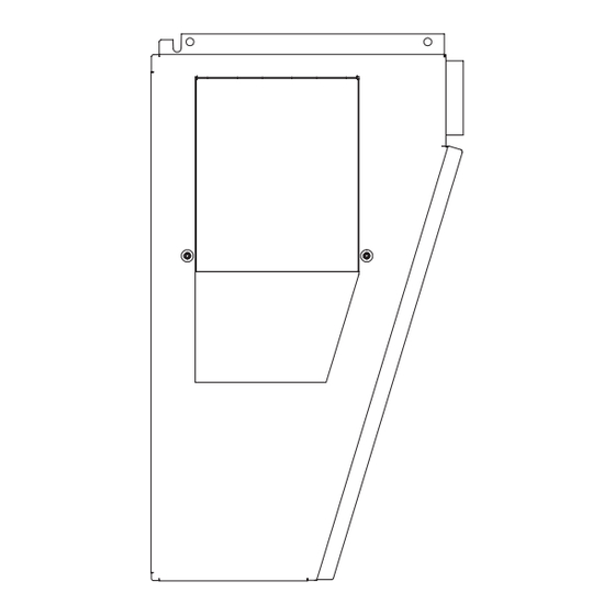
a) Remove the patch plate from the left side panel of the water cooler and install on the right side panel of the water fountain re-
using the two mounting screws. The two bottom screws from each side panel may be temporarily removed to improve access.
b) Remove the screws holding the waste drain tubes from the cooler tops. The shorter drain will be used on the water cooler and
the longer drain will be used on the water fountain. Make sure that the waste drain gaskets are properly installed.
6. Mount the water cooler on the right hanger.
7. Straighten the inlet "Water In" tube in the water fountain. Mount the water fountain on left side hanger while routing the "Water
In" tube through the access hole to the water cooler. Remove the plug from the "Drain/Remote Cold Water" connection and insert
the "Water In" tube.
8. All provided waste drain parts for field installation are packed in the water fountain. Assemble the drain per the appro-
priate roughing in drawing. The short leg of the crossover piece will be on the water cooler side. When the unit has an
internal waste trap, the trap should be wrapped with insulating tape to prevent sweating. The use of the 1 3/4" knockout
for a waste line is not recommended because of a potential conflict with ADA* toe space requirements. Check with your
local building code inspector for approval.
9. Install a shut off valve in water supply line. Remove the strainer from the cooler "Water Supply" tube. Solder 3/8" inlet tube exten-
sion (furnished) with lead free solder to "Water Supply" tube and insert the strainer in open end of extension. Connect extension
to shut off valve to allow access to strainer for service, this connection should not be a solder or flare joint. To ease removal of the
strainer, a sheet metal screw may be lightly threaded into the open end.
10. Rotate the fan blade by hand to see that it is free of obstructions.
11. Check the available power supply against the water cooler data plate to assure correct electrical service. Plug power supply cord
into wall outlet. The rear most 1 3/8" diameter knockout in the frame bottom is for an externally located electrical supply. Make
sure the knockout hole edge is smooth and free of any burrs. Use of a Heyco busing #2184 in the knocked out hole is recom-
mended in order to prevent damage to the service cord and to close up excess opening around the cord. Route the cord so it
does not interfere with ADA* space requirements.
12. To fill the cold water tank on the water cooler, open the water supply line shut-off and push any one of the front push-button to
allow water to flow to the bubbler. On The EE model, actuate the solenoid by holding one hand approximately 3 inches from the
infrared sensor. Run water until stream is free of bubbles.
13. To adjust bubbler stream:
a) All pushbutton models are equipped with a cartridge regulator. The KEP8ACSL and KEPACSL have a slot in the shelf below the
push-button. Insert a screwdriver in this slot to adjust regulator. Turn adjustment clockwise to increase stream height. To ac-
cess the KEPV8ACSL adjustment, remove the bezel and button from the front of the cooler.
0316
KEPACSL-EBF_036865-066
1
Advertisement
Table of Contents

Related Manuals for Franke KEP ACSL-EBF Series


Summary of Contents for Franke KEP ACSL-EBF Series
- Page 1 DRINKING FOUNTAIN INSTALLATION For All Universal Split Level KEP( )ACSL-EBF Series Drinking Fountains with Electronic Bottle Filler A. INSPECTION Inspect the water cooler, water fountain and cartons for evidence of rough handling and concealed damage. Damage claims should be filed with the carrier. B.
- Page 2 DRINKING FOUNTAIN INSTALLATION For All Universal Split Level KEP( )ACSL-EBF Series Drinking Fountains with Electronic Bottle Filler b) Electric eye (EE) models have a regulator built into the bubbler. If adjustment is needed, insert a 5/64" wrench approximately 1 1/8" into the bubbler nozzle opening until it bottoms out and is seated in an adjust screw. Turn the adjust screw clockwise to reduce the stream heigh or counterclockwise to increase the height.
- Page 3 DRINKING FOUNTAIN INSTRUCTIONS DRINKING FOUNTAIN ROUGH-IN MODELS: KEP8ACSL, KEP8ACSLEE, KEPF8ACSL, KEPF8ACSLEE, KEPV8ACSL, KEPVF8ACSL, KEADA8ACB, KEADA8ACBHF, KEADAF8ACB, KEADAF8ACBHF For All Universal Split Level KEP( )ACSL-EBF Series Drinking Fountains with Electronic Bottle Filler DRAIN CONFIGURATION RIGHT SIDE HIGH DRAIN CONFIGURATION RIGHT SIDE LOW WATER COOLER WATER FOUNTAIN LEFT SIDE PANEL...
- Page 4 DRINKING FOUNTAIN ROUGH-IN For All Universal Split Level KEP( )ACSL-EBF Series Drinking Fountains with Electronic Bottle Filler RIGHT SIDE LOW AFTER CONVERSION 0316 KEPACSL-EBF_036865-066...
- Page 5 DRINKING FOUNTAIN ROUGH-IN For All Universal Split Level KEP( )ACSL-EBF Series Drinking Fountains with Electronic Bottle Filler * On split level models, the Bottle Filler must be mounted on the low unit in order to meet CSA/ADA guidelines 0316 KEPACSL-EBF_036865-066...
- Page 6 DRINKING FOUNTAIN INSTALLATION For All Universal Split Level KEP( )ACSL-EBF Series Drinking Fountains with Electronic Bottle Filler This HAND-FREE BOTTLE FILLER is an extension of the Franke drinking fountains product line that mounts directly above our Universal Drinking Fountain. The wall requires a standard 2-outlet electrical receptacle to accommodate the electrical cords from both the fountain and the bottle filler.
-
Page 7: Section 1: Getting Started
SECTION 1: GETTING STARTED NOT PRE-DRILLED/BOTTLE FILLER KIT: If the unit is not pre-drilled or you purchased a BOTTLE FILLER retrofit KIT, go to next PAGE 8, STEP 1. PRE-DRILLED: If your unit was purchased pre-drilled at the factory as a COMBINATION, go to PAGE 10, STEP 2. -
Page 8: Section 2: Connecting The Water Line
SECTION 3: INSTALLATION WATER COOLER INSTALLATION INSTRUCTIONS, MODELS: KEPWSBF SECTION 2: CONNECTING THE WATER LINE DRINKING FOUNTAIN A. DRILLING HOLE IN THE TOP FOR WATER LINE CONNECTION NOT PRE-DRILLED 1. Disconnect power by UNPLUGGING unit. It might be necessary to remove the front panel to get access to the power. 2. - Page 9 ALIGN THIS EDGE WITH LEFT EDGE OF COOLER TOP 3 1/4 po [8.3cm] FROM SIDE 2 1/8 po [5.4cm] FROM BACK Mark this center point on the top. Remove the top from the cooler. Then drill a 7/8" [2.2cm] hole through the top at the marked centre point.
- Page 10 SECTION 2: CONNECTING THE WATER LINE (cont'd) DRINKING FOUNTAIN STEP 2: With the cooler top removed, find the tube going from the cooling tank outlet to the valve. The TEE fitting (supplied) will need to connect be- tween the cooling tank and valve. (Figure 3) Figure 3 Outlet Tube (insulated plastic) VALVE...
- Page 11 SECTION 2: CONNECTING THE WATER LINE (continuation) DRINKING FOUNTAIN STEP 6: Feed tubing up through the top and attach the top to the cooler. (Figure 7) ÉTAPE 6 Faire passer le tuyau dans le dessus et fixer ce dernier au refroidisseur. (Figure 10) Figure 7 0316 KEPACSL-EBF_036865-066...
- Page 12 SECTION 3: MOUNTING THE FRAME TO THE WALL STEP 1: Place rubber gasket on top of the cooler so it is centered left/right and against the wall. (Figure 11) STEP 2: Set the wall frame onto the gasket. Center it left/right and push it against the wall and mark hole locations for wall fasteners. The gasket will set the frame at the proper height.
- Page 13 SECTION 3: MOUNTING THE FRAME TO THE WALL (continuation) STEP 6: Attach Bottle Filler assembly to the frame using the four (4) vandal resistant torx screws. Leave the top cap off until after the program is set for this installation (Figure 15) Figure 15 Torx screws STEP 7:...
-
Page 14: Section 4: Program Guide
SECTION 4: PROGRAM GUIDE FOR ELECTRONIC BOTTLE FILLER Factory default settings are for: BOTTLES SAVED • an UNFILTERED unit BOUTEILLES SAUVÉES • a 20-second maximum run time 1. Top cap is set aside until program is complete. Remove top cap by unscrewing two (2) T15 torx screws, if needed. - Page 15 EXPLODED PARTS BREAKDOWN ELECTRONIC SPORTS BOTTLE FILLER 0316 KEPACSL-EBF_036865-066...
- Page 16 EXPLODED PARTS BREAKDOWN ELECTRONIC SPORTS BOTTLE FILLER 1. 036190-002 Alcove 2. 036691-001 Wrapper 3. 036686-001 4. 036049-002 Screw, flat head tapping 5. 036688-001 Tray, drip 6. 036695-001 Tray, grille drip 7. 036697-001 Bottom cap for drip tray 8. 036194-002 Button 9.
-
Page 17: Specifications
SPECIFICATIONS CHILLED DRINKING FOUNTAIN MODELS: SPLIT LEVEL UNIVERSAL MODELS: SINGLE UNIVERSAL Voltage 115 VAC±10%/1 PH/60 Hertz 115 VAC±10%/1 PH/60 Hertz Size 35 1/4" W, 18 5/8" D, 24 29/32" H 17 5/8" W, 18 5/8" D, 18 29/32" H Shipping Weight (Approx) 84 lbs. - Page 18 EXPLODED PARTS BREAKDOWN DRINKING FOUNTAIN To adjust stream height, insert a 1/8" flat blade screwdriver into the slotted hole as shown. The screwdriver will engage the stream height adjuster in the cartridge plunger. Turn clockwise to increase stream height or counter clockwise to reduce stream height. 0316 KEPACSL-EBF_036865-066...
-
Page 19: Parts Breakdown List
PARTS BREAKDOWN LIST DRINKING FOUNTAIN Item Single Split Level Single Description...............Chilled ......Chilled ...... Non-chilled Top ................031714-101 ....031714-101 ....031714-101 Bubbler ..............035607-108 ....103607-108 ....035607-108 Washer, under top ............ 028706-030 ....028706-030 ....028706-030 Locknut ..............026824-019 ....026824-019 ....026824--109 Bubbler nut W/ JG (John Guest)........ -
Page 20: Wiring Diagram
WIRING DIAGRAM WIRING DIAGRAM DRINKING FOUNTAIN Single KEP(__) series, Single KEP(_) Series Split Level KEP (__) series Split Level KEP(_)ACSL Series Franke Kindred Canada Limited Franke Commercial Systems 1000 Franke Kindred Road Midland, ON L4R 4K9 1.855.446.5663 Fax 1-866-227-3050 www.franke-commercial.com...
Need help?
Do you have a question about the KEP ACSL-EBF Series and is the answer not in the manual?
Questions and answers