Table of Contents
Advertisement
Quick Links
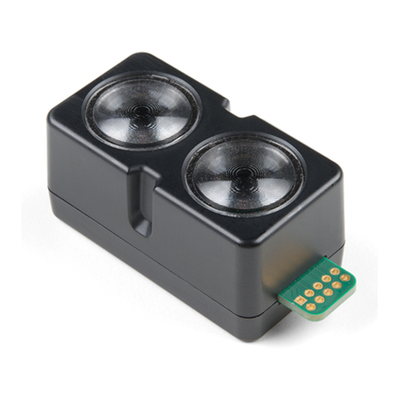
LIDAR-LITE V4 LED
OPERATION MANUAL AND
TECHNICAL SPECIFICATIONS
Specifications
Specification
Unit dimensions (L × W × H)
NOTE: Measurements do not
include an attached connector.
Weight
Operating temperature
Storage temperature
Power (operating voltage)
Current consumption
Input voltage (VIN)
Range
Resolution
Beam divergence
LED wavelength
Optical aperture
Update rate
Interface
Measurement repeatability
NOTE: As measured indoors to a
90% reflective target; 1 cm is
equivalent to 1 standard deviation.
Measurements were obtained
using high accuracy mode.
Device Dimensions
Measurement
52.2 x 24 x 21.2 mm (2.1 x 0.9 x
0.8 in.)
14.6 g (0.5 oz.)
-20 to 60°C (-4 to 140°F)
-40 to 85°C (-40 to 185°F)
4.75 to 5.25 Vdc
2 mA idle
85 mA during an acquisition
3.3 V Max
5 cm (1.97 in.) to 10 m (32.8 ft.)
1 cm (0.4 in.)
4.77 degrees
940 nm
14.9 mm
I2C: Greater than 200 Hz typical
ANT: Up to 200 Hz to a 90%
reflective target indoors at 2 m in
normal operating mode
I2C or ANT
®
Configurable for SPI with user
applications
± 1 cm to 2 m
± 2 cm to 4 m
± 5 cm to 10 m
52.17 mm (2.05 in.)
44.98 mm (1.77 in.)
10.6 mm (0.42 in.)
24.03 mm (0.95 in.)
1 mm (0.04 in.)
18 mm (0.71 in.)
21.35 mm (0.84 in.)
21.2 mm (0.83 in.)
Mounting Options
Cable tie: You can secure the device to your application using a
3.6 mm (0.14 in.) wide cable tie. You should route the cable
tie through the channel in the center of the device.
Double-sided tape: You can secure the bottom of the device to
your application using double-sided tape. For best results,
you should select a tape that has a high-strength bond.
Labeling Requirements
The LIDAR-Lite v4 LED device is an FCC-certified transmitter. If
you are integrating the device with another product, you must
ensure the FCC ID is visible from the outside of your product.
You are responsible for meeting any other labeling requirements
imposed by the FCC rules and any rules related to the
compliance of your end product.
Connections
LIDAR-Lite v4 LED Connection Diagram
The through-holes on the LIDAR-Lite v4 LED device are
arranged in 2 rows of 5 holes each, with a 2 mm pitch between
each connection.
The LIDAR-Lite v4 LED maximum signal level is 3.3 V. A signal
greater than 3.3 V will damage the device.
Pin
Pin Name
Function
VIN
5 V Power
GND
Ground
I2C SDA
I2C Data
I2C SCL
I2C Clock
NOTICE
V Max
5 V
--
3.3 V
3.3 V
August 2019
190-02533-00_0A
Advertisement
Table of Contents

Subscribe to Our Youtube Channel
Related Manuals for Garmin LIDAR-LITE V4 LED


Summary of Contents for Garmin LIDAR-LITE V4 LED
-
Page 1: Specifications
® Configurable for SPI with user NOTICE applications The LIDAR-Lite v4 LED maximum signal level is 3.3 V. A signal Measurement repeatability ± 1 cm to 2 m greater than 3.3 V will damage the device. ± 2 cm to 4 m NOTE: As measured indoors to a ±... -
Page 2: Operational Information
16-bit value within one transfer. See Obtaining of light. Measurements from the I2C Interface, page The LIDAR-Lite v4 LED contains an nRF52840 SoC from Nordic For a list of all available control registers, see Control Register Semiconductor. This SoC pairs an ARM Cortex-M4 processor List, page with 1 MB of flash memory and 256 KB of RAM. - Page 3 Other ANT capable devices can NOTE: You can use the DFU.zip file provided by Garmin or a connect to the LIDAR-Lite v4 LED to control it, receive data from custom DFU.zip file. it, and configure it wirelessly. ANT messages are sent and...
- Page 4 SCL. host controller, and the term LIDAR device to refer to the LIDAR-Lite v4 LED device acting as a slave on the I2C bus. The master sends an 8-bit data byte following the slave address, which loads the I2C control register on the LIDAR...
- Page 5 0x1B, page 6 0x1C R/W DETECTION_SENSITIVITY Peak detection threshold bypass 0x00 0x1C, page 6 0x30 LIB_VERSION Read Garmin software library version string -- 0x30, page 7 0x52 R/W CORR_DATA Correlation record data control 0x52, page 7 0x72 CP_VER_LO Coprocessor firmware version low byte...
- Page 6 0x18 Bit Function Reference overflow flag R/W Name Description Initial 0: Reference data has not overflowed Value 1: Reference data in correlation record has reached the maximum UNIT_ID_2 Unit ID, byte 2 value before overflow (this occurs when taking measurements with UNIT_ID_2_UNLOCK Write unit ID 2 for I2C biasing enabled) address unlock...
- Page 7 0xFF: Always on. The coprocessor is not turned off, allowing for R/W Name Description Initial Value the fastest measurements possible. LIB_VERSION Read Garmin software library NOTE: You must disable HIGH_ACCURACY_MODE before you adjust the power mode. version string Bit Function...
- Page 8 Bit Function You should connect the 10-pin J-Link debugging probe to the 7:0 0x00: Use RAM storage only. LIDAR-Lite v4 LED device as shown in the diagram and table 0x11: Use FLASH/NVM storage. Any register that supports both below. read and write operations is stored in NVM and persists over power cycles.
-
Page 9: Troubleshooting
Arduino AG. The BLUETOOTH ® word mark and logos are owned by the Bluetooth SIG, Inc. and any use of such marks by Garmin is under license. J-Link is a trademark of SEGGER Microcontroller GmbH. Nordic Semiconductor ®... - Page 10 © 2019 Garmin Ltd. or its subsidiaries support.garmin.com...
Need help?
Do you have a question about the LIDAR-LITE V4 LED and is the answer not in the manual?
Questions and answers