
Related Manuals for MOBA Pave-TM


Summary of Contents for MOBA Pave-TM
- Page 1 USER MANUAL MOBA Pave-TM Automatic system for continuous layer thickness measurements Related documents: Specification 04-26-10020-A01 CE declaration of conformity ENGLISH...
- Page 2 All rights reserved. No part of these documents may be reproduced or transmitted for any purpose without express written permission from MOBA, irrespective of the manner or the means by which this occurs. Copyright by MOBA Mobile Automation AG...
-
Page 3: Table Of Contents
Table of contents Table of contents General information ..................6 Information about the operating manual ..........6 Limitation of liability ................6 Structure of the safety notices ..............7 Spare parts .................... 8 ... - Page 4 Mechanical installation ................. 27 8.1.1 Mounting display ..................28 8.1.2 Mounting of ultrasonic sensors (MOBA Sonic-Ski Plus) ......29 8.1.3 Mounting of the “Pave-TM” control box ............. 34 8.1.4 Mounting the MTSC-202 signal converter ..........35 8.1.5 Mounting the MTSC-201 signal converter ..........37 ...
- Page 5 Table of contents Area calculation settings ................53 Operation ....................56 10.1 System alignment ..................56 10.2 Starting, stopping and resetting the area calculation .......58 10.3 Resetting the distance ................59 Factory settings (“Marker reset”) ..............60 ...
-
Page 6: General Information
In this case, your MOBA supplier will have a current copy of the operating manual ready for you. We accept no liability for faults, failures and resulting damages The figures in this operating manual are provided for better understanding. -
Page 7: Structure Of The Safety Notices
General information The manufacturer accepts no liability for damages resulting from: • Improper mounting and installation • Failure to observe the operating manual • Unintended and improper use • Use outside of the operating limits • Use of insufficiently qualified / trained personnel •... -
Page 8: Spare Parts
1.5 Guarantee provisions This operating manual contains no guarantees. The guarantee provisions are part of the MOBA MOBILE AUTOMATION AG (MOBA) “Terms and Conditions of Sale and Delivery”. 1.6 Final decommissioning / disablement During the final decommissioning, the components are to be rendered unusable to protect against recommissioning, particularly by unauthorised third parties. -
Page 9: Disposal
General information 1.7 Disposal CAUTION! Risk of injury from improper disposal! The burning of plastic parts releases poisonous gases which may cause illness in persons. • Properly dispose of product in accordance with the applicable, national, country-specific disposal regulations. CAUTION! Risk of injury from improper disposal! Careless disposal enables unauthorised persons to use the product improperly. -
Page 10: Intended Use Of The Machine
The product is designed and constructed exclusively for the intended purpose described here: MOBA Pave-TM is an automatic system for continuous measurements of the layer thickness and temperature visualization during asphalt construction. Any use other that listed here as well as any use that deviates from the technical data is considered to be non-intended and improper use. -
Page 11: Operating Limits
Intended use of the machine 2.2 Operating limits The product is designed for use in an atmosphere appropriate for permanent human habitation. The product must not be used in aggressive or explosive environments. Local safety authorities and safety management personnel are to be contacted by the system owner before working in hazardous environments, near electrical systems or in similar situations. -
Page 12: Security
Security Security The safety notices and warning notices listed here and in the following chapters of this manual must be observed to reduce health hazards and avoid dangerous situations. 3.1 Contents of the operating manual Any person who is charged with performing work on or with the product must have read/ the operating manual before beginning work. -
Page 13: Operating Personnel
Security 3.3 Operating personnel WARNING! Danger from inadequate qualification! Improper use of the product can result in serious personal injuries and material damage. • Only permit work with the product to be performed by persons who are sufficiently qualified for the tasks described in the respective chapters of this operating manual. - Page 14 Security CAUTION! Risk of injury from protruding machine parts! Retrofitted system components (e.g. sensors) can protrude over the typical machine dimensions. This can result in injuries and material damage. • Make certain that the machine is operated by a qualified and experienced operator.
-
Page 15: Safety Equipment
Security 3.5 Safety equipment The product has no higher-level safety equipment of its own. 3.6 Behaviour in the event of dangerous situations and accidents Preventative measures: • Always be prepared for accidents and fire! • Have first aid gear (first aid box, blankets, etc.) and fire extinguishers accessible at all times. -
Page 16: Transport, Packaging And Storage
Transport, packaging and storage Transport, packaging and storage 4.1 Transport inspection To ensure sufficient protection during shipment, the products are carefully packaged. Upon receipt of delivery, immediately inspect for completeness and for transport damage. In the event of externally recognisable transport damage, proceed as follows: •... -
Page 17: Storage
Transport, packaging and storage 4.3 Storage Only store the product in well ventilated, dry rooms. During storage, protect against moisture. Use the original packaging for this purpose if possible. Avoid large temperature fluctuations during storage. The formation of condensation can impair the function. During storage, observe the temperature limit values of the products. -
Page 18: Structure And Function
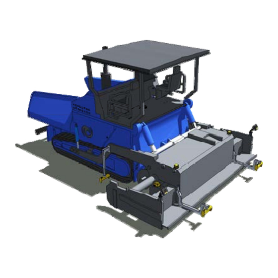
Structure and function Structure and function The MOBA Pave-TM layer thickness measurement system can be integrated into standard, mobile road pavers. Fig.5-1: Installation example (scheme) Graphic display / control panel Ultrasonic sensor Sonic-Ski plus (incl. holder) Ultrasonic sensor Sonic-Ski plus (incl. holder) Wire rope sensor “Pave-TM”... - Page 19 Structure and function The MOBA GDC-320 control panel is the interface between the operator and the layer thickness measurement system. Fig.5-2: Control panel The Ski Plus is an ultrasonic sensor which scans the subgrade for the layer thickness calculation (distance measurement).
- Page 20 Structure and function The temperature sensor selectively measures the temperature of the material at any given point. Fig.5-6: IR temperature sensor...
-
Page 21: Operating And Display Elements
Operating and display elements Operating and display elements 6.1 Display/operating elements on the control panel Fig.6-1: Control panel Graphic display (colour graphics) Handwheel Function buttons (membrane keyboard) Entering data or navigating can be done via the function buttons or the handwheel. -
Page 22: Handwheel
Operating and display elements 6.3 Handwheel Fig.6-3: Function of handwheel Turn to navigate in a submenu or to set values/parameters. The “active” menus and functions are highlighted in the display. Press to confirm the set values. 6.4 LED indicators Fig.6-4: Function of handwheel Status indicator LED 1-3: LED 1 flashes if one or several markers are in a non-defined range. -
Page 23: Display Settings / Led Settings
Operating and display elements 6.5 Display settings / LED settings In the main menus, the display brightness can be changed via a task bar and the LED switched on and off. Fig.6-5: Display brightness Press the “Settings” (1) button and keep it pressed. Fig.6-6: LCD/LED task bar Adjust the display brightness by pressing the “Brightness”... -
Page 24: Main Menus
Main menus Main menus 7.1 Layer thickness In the “Layer thickness” menu, the calculated layer thickness and the currently selected filter are displayed. Fig.7-1: “Layer thickness” menu No filter active Distance filter active Dead band filter active Average filter active... -
Page 25: Temperature
Main menus 7.2 Temperature In the temperature menu, the currently measured selective individual temperature is displayed graphically and numerically. Fig.7-2: “Temperature” menu 7.3 Distance In the “Distance” menu, two independent, resettable distances are displayed (A above, B below). Fig.7-3: “Distance” menu... -
Page 26: Area Calculation
Main menus 7.4 Area calculation The “Area calculation” menu displays the total screed width, the measure distance, and the calculated area (A). Fig.7-4: “Area calculation” menu 7.5 Overview menu Calling up the overview menu! NOTE! The overview menu can only be accessed if it has been activated. The overview menu displays the main process data. -
Page 27: Mounting
Mounting Mounting WARNING! Danger from inadequate qualification! Improper use of the product can result in serious personal injuries and material damage. • Only permit work with the product to be performed by persons who are sufficiently qualified for the tasks described in the respective chapters of this operating manual. -
Page 28: Mounting Display
Important note regarding proper function! NOTE! The MOBA Pave-TM system can be installed on various types of machines. For this reason, only basic mounting and corresponding requirements are described in this manual. Important note regarding proper function! -
Page 29: Mounting Of Ultrasonic Sensors (Moba Sonic-Ski Plus)
The sensors themselves must be attached laterally to the direction of travel. Important note regarding proper function! NOTE! The following must be observed for the MOBA Pave-TM system to operate as intended: • There must be no material below the front sensors. If necessary, install a protective plate or similar. - Page 30 Mounting Fig.8-3: Installation example (scheme) Ultrasonic sensor with holder on the tow arm (left / right) Ultrasonic sensor with holder on the screed (left / right) Moving direction...
- Page 31 Mounting Fig.8-4: Installation example (scheme) Ultrasonic sensor with holder Screed rear edge Moving direction Distance of the front sensor to the screed rear edge (min. 50 cm) Distance of the rear sensor to the screed rear edge (min. 50 cm) The ultrasonic sensors should be attached with as little distance as possible to the subgrade.
- Page 32 Mounting Both rear ultrasonic sensors must be mounted on the left and right of the screed via a holder designed in line with the paver type or adapted to it. An example of mounting is described below. Fig.8-6: Ultrasonic sensor on screed Mount the holder (6) at the mounting position provided on the paver.
- Page 33 Mounting Fig.8-7: Ultrasonic sensor on tow Screw in the mounting flange (8) at the mounting position provided on the tow arm. Push the holder onto the mounting flange and tighten the clamp lever (9) Loosen the star knob screws (11). Insert the sensor (10) into the holding fixture in the installation position provided (laterally to the direction of travel).
-
Page 34: Mounting Of The "Pave-Tm" Control Box
Mounting 8.1.3 Mounting the “Pave-TM” control box The control box can be mounted on any readily accessible location on the machine. NOTE! Positioning of the control box! The supply lines to individual system components must not be squeezed or torn off by moving parts. -
Page 35: Mounting The Mtsc-202 Signal Converter
Mounting 8.1.4 Mounting the MTSC-202 signal converter The signal converter should be mounted on a readily accessible location on the machine that offers as much protection as possible. Mounting with magnetic feet Fig.8-9: Mounting the magnetic feet Connect the signal converter (1), the spacer sleeves (2) and the magnetic feet (3) with self-locking M4x8 screws (4). - Page 36 Mounting Mounting with fastening screws Fig.8-11: Screwing on signal converter Prepare the necessary fixing holes at the mounting position (9). Screw on the signal converter (7) with the self-locking M4x12 screws (8) at the mounting position provided (9).
-
Page 37: Mounting The Mtsc-201 Signal Converter
Mounting 8.1.5 Mounting the MTSC-201 signal converter The signal converter should be mounted on a readily accessible location on the machine that offers as much protection as possible. NOTE! Positioning of the sensor! The MTSC-201 must be connected directly to the IR temperature sensor. - Page 38 Mounting Fig.8-13: Attaching the signal converter Attach the signal converter (5) at the mounting position provided (6). Mounting with fastening screws Fig.8-14: Screwing on signal converter Prepare the necessary fixing holes at the mounting position (9). Screw on the signal converter (7) with the self-locking M4x12 screws (8) at the mounting position provided (9).
-
Page 39: Mounting Of The "Pave-Tm" Control Box
Mounting 8.1.6 Mounting the “Pave-TM” connection box The connection box should be mounted on a readily accessible location on the machine that offers as much protection as possible. Mounting with magnetic feet Fig.8-15: Mounting the magnetic feet Connect the signal converter (1), the spacer sleeves (2) and the magnetic feet (3) with self-locking M4x8 screws (4). - Page 40 Mounting Mounting with fastening screws Fig.8-17: Screwing on signal converter Prepare the necessary fixing holes at the mounting position (9). Screw on the signal converter (7) with the self-locking M4x12 screws (8) at the mounting position provided (9).
-
Page 41: Mounting Of The Ir Temperature Sensor
Mounting 8.1.7 Mounting the IR temperature sensor The IR temperature sensors are used to selectively monitor material temperature. This can be done at a suitable and easily accessible position on the material bucket or on the paver auger. The infrared surface measurement works the most effectively when measuring is done where material is constantly moving. - Page 42 Mounting Fig.8-20: Mounting the temperature sensor Fig.8-21: Mounting the temperature sensor Depending on the selected position, mount the holder with the fastening screws (4) onto the paver (5).
-
Page 43: Mounting Of The Wire Rope Sensor
Mounting Fig.8-22: Mounting the temperature sensor By loosening both bolts (6), the sensor can still be aligned after mounting on the paver. 8.1.8 Mounting the wire rope sensor The screed width can be measured dynamically with the help of wire rope sensors. They should be installed protected against heat and moisture. -
Page 44: Electrical Installation
Mounting 8.2 Electrical installation DANGER! Danger from electric current! During work with the product in the immediate vicinity of electrical systems (e.g. overhead lines or electrical railways), there is a risk of electric shock and thus life-threatening danger. • Maintain a sufficient safety distance to electrical systems. •... - Page 45 Mounting Fig.8-24: System overview “Pave-TM” control box HMImc GDC-320 Sonic-Ski Plus “SKIS-1500” MTSC-201 (temperature) Wire rope sensor Connection box, rear “Pave-TM” sensors IR temperature sensor GPS smart antenna Connection box, GDC-320, “Pave-TM” display...
- Page 46 Mounting 04-02-XXXXX cable, M12, CAN Length: 1m to 10m 04-02-02624 coil cable, CAN, 6m CAN connection for front ultrasonic sensors Length: 6m (extended) 04-02-02620 coil cable, CAN, 6m CAN connection for rear ultrasonic sensors Length: 6m (extended) 04-02-035XX cable, M12, CAN Length: 3m to 15m 05-02-02611 cable set 04-02-035XX...
-
Page 47: Initial Commissioning
The main screen appears when the system is switched on. The yellow status bar indicates the charge state. Once the system is started, the “Layer thickness measurement” menu is automatically called up. The addressing of the MOBA GDC- 320 colour display is displayed in the top right corner. -
Page 48: Initial Commissioning / System Settings
Initial commissioning 9.2 Initial commissioning / system settings Once the system is mounted and started, all system settings must be executed. All settings must be executed for both the right and left side of the system and can be changed at any time. 9.3 Layer thickness measurement CAUTION! Correct distances of the sensor centres! - Page 49 Initial commissioning Fig.9-3: System settings, “Layer thickness settings” menu Distance of the sensor to the screed rear edge (min. 100 mm, max. 9999 mm) C/D Distance of the sensor to the ground Additional warning notices: Sensor not connected Sensor out of operating range Fig.9-4: System settings, “Layer thickness measurement”...
-
Page 50: Filter Settings
Initial commissioning 9.4 Filter settings Fig.9-5: System settings, “Filter settings” submenu Open “Filter settings” submenu by pressing the “Filter” (2) button. Fig.9-6: “Filter settings” submenu No filter is active for this setting. It is NOT recommended to adopt this setting; it is only used for test purposes! The dead band filter is the recommended filter type if a DEAD BAND displacement signal from the paver is not available. -
Page 51: Temperature Measurement Settings
Initial commissioning Fig.9-7: System settings, “Filter settings” submenu Select the appropriate menu item by turning the handwheel (3) and set the value. Press the handwheel (3) and confirm the value. Leave the menu by pressing the “Back” button (4). 9.5 Temperature measurement settings Fig.9-8: System settings, “Temperature measurement”... - Page 52 Initial commissioning Fig.9-10: “Temperature settings” submenu Set the required temperature filter time by turning the handwheel (2) (0s/OFF -55s). Press the handwheel (2) and confirm the value. Leave the menu by pressing the “Back” button (3). The temperature filter is a maximum value filter. An increasing temperature is displayed immediately.
-
Page 53: Area Calculation Settings
Initial commissioning 9.6 Area calculation settings Retract the screed completely! NOTE! For the first commissioning the screed must be completely retracted before executing the required system settings. Fig.9-11: “Area calculation” system settings Open “Area calculation” settings" submenu by pressing the “Settings” (1) button. - Page 54 Initial commissioning Fig.9-13: Setting the “Basic screed width” Select the “Basic screed width” (C) menu item to be set by turning the handwheel (2) and set the current value (0mm 9999 mm). – Press the handwheel (2) and confirm the value. Select/activate the “Attachment elements”...
- Page 55 Initial commissioning Fig.9-15: Open “Wire rope sensor” submenu Open “Wire rope sensor settings” submenu by pressing the “Settings” (5) button. The “Settings” function will only appear if one of the menu items “Basic screed width” or “Attachments” is selected. Fig.9-16: Selecting wire rope sensor Select the installed wire rope sensor type by turning the handwheel (6).
-
Page 56: Operation
Operation 10 Operation WARNING! Danger from inadequate qualification! Improper use of the product can result in serious personal injuries and material damage. • Only permit work with the product to be performed by persons who are sufficiently qualified for the tasks described in the respective chapters of this operating manual. - Page 57 Operation Filling in of material starts. Screed floats! Fig.10-1: Screed floats Screed has floated up Fig.10-2: Screed has floated up As soon as the screed has floated up, the layer thickness must be measured manually! Fig.10-3: Aligning the system Turn or press the handwheel (2) in the “Layer thickness” menu. An input field (1) will appear on the right side of the display.
-
Page 58: Starting, Stopping And Resetting The Area Calculation
Operation System alignment not yet executed! NOTE! If the system alignment has not yet been executed, this is displayed by a “Warning notice” in the top left display corner: 10.2 Starting, stopping and resetting the area calculation Changes to the area calculation! NOTE! Changes to the area calculation are automatically adopted for the left and right system sides! -
Page 59: Resetting The Distance
Operation Press handwheel (2) and confirm the value. Leave the menu by pressing the “Back” button (3). 10.3 Resetting the distance Changes to the distance! NOTE! When resetting distance A the values of both system sides are reset. Resetting distance B only affects the system side operated in each case! Fig.10-5: Resetting the distance Turn or press the handwheel (2) in the “Distance”... -
Page 60: Factory Settings ("Marker Reset")
Factory settings (“Marker reset”) 11 Factory settings (“Marker reset”) To reset the system again in full in the delivery state (“Marker reset”), please proceed as follows. “Marker reset” (reset system)! NOTE! After a “Marker reset” the saved data and settings from both system sides are irretrievably deleted! Fig.11-1: Calling up the “Marker reset”... - Page 61 Factory settings (“Marker reset”) Green! Marker at factory setting. Yellow! Marker not at factory setting. Red! Marker defective. Fig.11-3: Execute “Reset” To reset parameters, press the “RESET” button (2). After reset leave the menu by pressing the “Exit” (3) button.
-
Page 62: Service And Maintenance
Service and maintenance 12 Service and maintenance DANGER! Danger from moving machine/components! Serious injuries from moving (driving) machines or moving components. • There must not be any people/objects in the danger area of the machine. • Voltage-carrying components must be disconnected from the power supply. -
Page 63: Maintenance
Risk of scratching sensitive surfaces. • Do not use any products with obvious signs of damage. 12.2 Maintenance The device should be inspected for correct function at regular intervals. 12.3 Repair In case the device becomes damaged or worn, contact your MOBA dealer. -
Page 64: Malfunctions/Errors
Malfunctions/Errors 13 Malfunctions/Errors DANGER! Danger from moving machine/components! Serious injuries from moving (driving) machines or moving components. • There must not be any people/objects in the danger area of the machine. • Voltage-carrying components must be disconnected from the power supply. •... -
Page 65: Sensor Error
Malfunctions/Errors 13.1 Sensor errors Display Error If one of the sensors does not provide valid values through an error, this is displayed by a dotted line. Fig.13-1: “Invalid value” As soon as a sensor is outside its operating range, the “OUT” notice will appear in the display. -
Page 66: Terminal Protocol
Terminal protocol 14 Terminal protocol Fig.14-1: “Terminal protocol, example 1”... - Page 67 Terminal protocol Fig.14-2: “Terminal protocol, example 2”...
- Page 68 Terminal protocol Fig.14-3: “Terminal protocol, example 3”...
-
Page 69: Technical Data
Technical data 15 Technical data Related documents! NOTE! Further, important technical data can be found in the further applicable documents. A listing of all other applicable documents can be found on the front page of this manual. 15.1 “GDC-320” control panel Operating voltage 32V DC …... - Page 70 Technical data Assignment of device socket n.c. + operating voltage out GND out CAN1+ CAN1-...
-
Page 71: Notes
Notes 16 Notes... - Page 72 MOBA Mobile Automation AG MOBA Mobile Automation AG MOBA-ISE Mobile Automation SL Kapellenstrasse 15 Freiberger Strasse 67-71 Polígono Industrial Plà de la 65555 Limburg / Germany 01159 Dresden / Germany Bruguera C/Bruguedà, 6 Phone: +49 6431 9577-0 Phone: +49 351 40908-0 08211 Castellar del Vallés,...
Need help?
Do you have a question about the Pave-TM and is the answer not in the manual?
Questions and answers