Bryant B Series Service And Maintenance Procedures Manual
Upflow/horizontal, variable-speed, 2-stage, induced-combustion furnaces
Hide thumbs
Also See for B Series:
Table of Contents
Advertisement
NOTE: Read the entire instruction manual before performing any
service or maintenance.
This symbol → indicates a change since the last issue.
These procedures are for size 60,000 through 117,000 Btuh units.
Index
SAFETY CONSIDERATIONS .....................................................1
PROCEDURE ...........................................................................2
CARE AND MAINTENANCE..................................................2-5
Air Filter Arrangement..........................................................2-3
Blower Motor and Wheel.........................................................3
Cleaning Heat Exchanger......................................................4-5
Electrical Controls and Wiring.................................................5
Troubleshooting ........................................................................5
Application Wiring Diagrams ..................................................6
Furnace Wiring Diagram ..........................................................7
Service Label ............................................................................8
Troubleshooting Guide .............................................................9
SAFETY CONSIDERATIONS
Installing and servicing heating equipment can be hazardous due to
gas and electrical components. Only trained and qualified person-
nel should install, repair, or service heating equipment.
Untrained personnel can perform basic maintenance functions
such as cleaning and replacing air filters. All other operations must
be performed by trained service personnel. When working on
heating equipment, observe precautions in the literature, tags, and
labels attached to or shipped with the unit and other safety
precautions that may apply.
In the United States, follow all safety codes including the National
Fuel Gas Code (NFGC) NFPA 54-1996/ANSI Z223.1-1996. In
Canada, refer to CAN/CGA-B149.1- and .2-M95 National Stan-
dard of Canada, Natural Gas and Propane Installation Codes
(NSCNGPIC). Wear safety glasses and work gloves. Have fire
extinguisher available during start-up and adjustment procedures
and service calls.
Recognize safety information. This is the safety-alert symbol
When you see this symbol on the furnace and in instructions or
manuals, be alert to the potential for personal injury.
→
Understand the signal words DANGER, WARNING, CAUTION
and NOTE. These words are used with the safety-alert symbol.
DANGER identifies the most serious hazards which will result in
severe personal injury or death. WARNING signifies a hazard
which could result in personal injury or death. CAUTION is used
to identify unsafe practices which would result in minor personal
injury or product and property damage. NOTE is used to highlight
suggestions which will result in enhanced installation, reliability,
or operation.
service and
maintenance procedures
UPFLOW/HORIZONTAL,
VARIABLE-SPEED, 2-STAGE,
INDUCED-COMBUSTION FURNACES
Page
.
-1-
Series B or C
Cancels: SP04-50
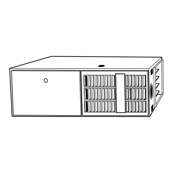
Fig. 1-Model 333BAV or 333JAV Horizontal
®
ama
A PP R O VED
R
Fig. 2-Model 333BAV or
REGISTERED
QUALITY SYSTEM
WARNING: The ability to properly perform mainte-
nance on this equipment requires certain expertise, me-
chanical skills, tools, and equipment. If you do not
possess these items, do not attempt to perform any
maintenance on this equipment other than those proce-
dures recommended in the User's Manual. A FAILURE
TO FOLLOW THIS WARNING COULD RESULT IN
POSSIBLE DAMAGE TO THIS EQUIPMENT, SERI-
OUS PERSONAL INJURY, OR DEATH.
333BAV
333JAV
SP04-57
7-99
A95137
A94085
333JAV Upflow
Advertisement
Table of Contents

Related Manuals for Bryant B Series


Summary of Contents for Bryant B Series
-
Page 1: Table Of Contents
service and 333BAV maintenance procedures 333JAV Series B or C UPFLOW/HORIZONTAL, VARIABLE-SPEED, 2-STAGE, INDUCED-COMBUSTION FURNACES Cancels: SP04-50 SP04-57 7-99 NOTE: Read the entire instruction manual before performing any service or maintenance. This symbol → indicates a change since the last issue. These procedures are for size 60,000 through 117,000 Btuh units. -
Page 2: Electrostatic Discharge (Esd) Precautions Procedure
ELECTROSTATIC DISCHARGE (ESD) PRECAUTIONS WARNING: Turn off the gas and electrical supplies to PROCEDURE the unit before performing any maintenance or service on it. Follow the operating instructions on the label attached CAUTION: Electrostatic discharge can affect electronic to the furnace. A failure to follow this warning could components. -
Page 3: Blower Motor And Wheel
TABLE 1—UPFLOW/HORIZONTAL FILTER SIZE The following steps should be performed by a qualified service INFORMATION (IN.) technician: The motors have prelubricated sealed bearings and require no FILTER SIZE† FURNACE FILTER CASING WIDTH TYPE lubrication. Side Return Bottom Return 14-3/16 (1) 16 X 25 X 1* (1) 14 X 25 X 1 Cleanable Remember to disconnect the electrical supply before removing (1) 16 X 25 X 1 (1) 20 X 25 X 1* Cleanable access doors. -
Page 4: Cleaning Heat Exchanger
→ 18. Check for proper blower operation in heating and cooling. C. Cleaning Heat Exchanger The following steps should be performed by a qualified service technician: NOTE: Deposits of soot and carbon indicate the existence of a problem which needs to be corrected. Take action to correct the problem. -
Page 5: Electrical Controls And Wiring
8. After cleaning flue openings, clean flue collector. Check NOTE: Be aware that measurement of current (amperes) and sealant on flue collector to ensure that it has not been power (watts) for the ICM2+ variable-speed motor will be accurate damaged. If new sealant is needed, contact your dealer or only when the meter provides true root-mean-square (RMS) distributor. -
Page 6: Application Wiring Diagrams
FIELD 24-V WIRING FIELD 115-, 208/230-, 460-V WIRING FACTORY 24-V WIRING FACTORY 115-V WIRING NOTE 2 1-STAGE THERMOSTAT FIVE FIELD-SUPPLIED TERMINALS WIRE FUSED DISCONNECT THREE-WIRE 115-V FIELD- 208/230- OR HEATING- SUPPLIED 460-V ONLY DISCONNECT THREE PHASE 208/230-V W/W1 SINGLE NOTE 1 PHASE Y/Y2 JUNCTION... -
Page 7: Furnace Wiring Diagram
—7—... -
Page 8: Service Label
SERVICE If status code recall is needed, do not remove power or blower door. Briefly remove and then reconnect one main limit wire to display stored status code. LED CODE STATUS CONTINUOUS OFF - Check for 115VAC at L1 and L2, and 24VAC at SEC1 and SEC2. CONTINUOUS ON - Control has 24VAC power. -
Page 9: Troubleshooting Guide
TROUBLESHOOTING NOTES: WARNING Refer to information label on blower compartment door GUIDE for procedure for use of LED status codes and problem solving suggestions. LED indicator is viewed through window in blower ELECTRICAL SHOCK HAZARD compartment door. If 115-vac power is de-energized or interrupted during ONLY QUALIFIED AND TRAINED a call for heat, the indoor blower will run for 90 sec SERVICE PERSONNEL SHOULD... - Page 10 —10—...
- Page 11 —11—...
- Page 12 Course descriptions and schedules are in our catalog. CALL FOR FREE CATALOG 1-800-962-9212 [ ] Packaged Service Training [ ] Classroom Service Training A94328 © 1999 Bryant Heating & Cooling Systems 7310 W. Morris St. Indianapolis, IN 46231 —12— Printed in U.S.A. sp0457 Catalog No. 5333-304...
Need help?
Do you have a question about the B Series and is the answer not in the manual?
Questions and answers